G7S-3A3B 24VDC Omron, G7S-3A3B 24VDC Datasheet
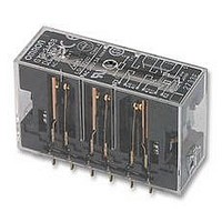
G7S-3A3B 24VDC
Specifications of G7S-3A3B 24VDC


Related parts for G7S-3A3B 24VDC


G7S-3A3B 24VDC Summary of contents
Page 1
... Removes relay from sockets DIN rail mounting track (1.64 ft) length 1 m (3.28 ft) length Spacer End plate Contact form Rated voltage (V) 4PST-NO + DPST-NC 24 VDC 3PST-NO + 3PST-NC G7S Part number G7S-4A2B DC24 G7S-3A3B DC24 Part number P7S-14F P7S-14A P7S-14P P7S-A10 P7S-B PFP-50N PFP-100N PFP-S PFP-M ...
Page 2
... ( 158 F) no icing – (- 158 F) no icing 35% to 85% RH 35% to 85% RH Approx G7S Max. voltage Power consumption 110% (V) Approx. 0.8 W Inductive load (cos = 0.4, L ms) ...
Page 3
... Dielectric strength 2000 VAC for 1 min. between terminals G7S I (Current) Terminal Installation/Internal Connection Diagram (Bottom View) 22.5 max. G7S-4A2B (0.89) 24 VDC 37 max. (1.46) G7S-3A3B 5 min. 24 VDC G7S Insulation resistance 1000 M min. (See note.) Cross-section of Mounting Holes Fourteen, 1.8 dia. 3 ...
Page 4
... With Safety Relay Mounted 39 max. (1.54 31.3 47 max. (1.85) 90.5 max. 40 max. (3.56) (1.57) 61.5 max. (2.42) G7S Terminal Installation/Internal Connection Diagram (Top View) Cross-section of Mounting Holes Terminal Installation/Internal Connection Diagram (Bottom View) G7S-4A2B Cross-section of Mounting Holes G7S-3A3B (0.83) (2.24) ...
Page 5
... Two, 6.5 dia x 7.9 deep 23 max. 261 max. (10.28) 59.2 19.3 35 (1.38 (0.59) Terminal Installation/Internal Connection Diagram (Bottom View) G7S-4A2B Cross-section of Mounting Holes G7S-3A3B Fourteen, 1.8 dia. Four, C0.5 81 max. (3.19) 1.6 (0.06) G7S Two, 3.6 dia. 5 ...
Page 6
... For common precautions when using and handling relays, consult Omron. Contacts The coil terminals have polarity (positive and negative).Operation is not possible if these are connected in reverse. Specifications subject to change without notice. G7S OMRON CANADA, INC. 885 Milner Avenue Scarborough, Ontario M1B 5V8 416-286-6465 Printed in U.S.A. ...