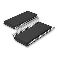
LV8741V-TLM-E ON Semiconductor, LV8741V-TLM-E Datasheet - Page 2

LV8741V-TLM-E
Manufacturer Part Number
LV8741V-TLM-E
Description
Motor / Motion / Ignition Controllers & Drivers STEPPING MOTOR
Manufacturer
ON Semiconductor
Datasheet
1.LV8741V-TLM-E.pdf
(25 pages)
Specifications of LV8741V-TLM-E
Motor Type
DC
No. Of Outputs
2
Driver Case Style
SSOP
No. Of Pins
44
Operating Temperature Range
-20°C To +85°C
Svhc
No SVHC (20-Jun-2011)
Base Number
8741
Rohs Compliant
Yes
Lead Free Status / Rohs Status
Details
Available stocks
Company
Part Number
Manufacturer
Quantity
Price
Company:
Part Number:
LV8741V-TLM-E
Manufacturer:
ON Semiconductor
Quantity:
1 550
Part Number:
LV8741V-TLM-E
Manufacturer:
SANYO/三洋
Quantity:
20 000
Continued from preceding page.
*1 Specified circuit board : 90×90×1.7mm
*2 For mounting to the backside by soldering, refer the precautions.
Recommended Operating Conditions at Ta = 25°C
Electrical Characteristics at Ta = 25°C, V M = 24V, V CC = 5V, VREF = 1.5V
Allowable power dissipation 1
Allowable power dissipation 2
Operating temperature
Storage temperature
Supply voltage range 1
Supply voltage range 2
VREF input voltage range
Standby mode current drain 1
Current drain 1
Standby mode current drain 2
Current drain 2
V CC low-voltage cutoff voltage
Low-voltage hysteresis voltage
Thermal shutdown temperature
Thermal hysteresis width
Output on-resistance
Output leakage current
Diode forward voltage 1
Diode forward voltage 2
Logic pin input current
Logic high-level input voltage
Logic low-level input voltage
Current
selection
reference
voltage level
Chopping frequency
Current setting reference voltage
VREF pin input current
Parameter
Parameter
Parameter
W1-2-phase
drive
1-2 phase drive
1-2 phase (full
torque) drive
2 phase drive
3
Pd max1
Pd max2
: glass epoxy printed circuit board
VthV CC
Symbol
Symbol
Symbol
I CC stn
VthHIS
VRF00
VRF01
VRF10
VRF11
I O leak
Fchop
VREF
∆TSD
IMstn
Ronu
Rond
V IN H
V IN L
Topr
V CC
Tstg
TSD
VD1
VD2
I IN H
I IN L
I CC
V M
Iref
IM
Independent IC
* Our recommended two-layer substrate *1, *2
ST = ”L”
ST = ”H”, OE = ”H”, no load
ST = ”L”
ST = ”H”, OE = ”H”, no load
Design guarantee
Design guarantee
I O = 1.5A, Upper-side on resistance
I O = 1.5A, Lower-side on resistance
ID = -1.0A
ID = -1.5A
V IN = 0.8V
V IN = 5V
Step 0(When initialized : channel 1
comparator level)
Step 1 (Initial state+1)
Step 2 (Initial state+2)
Step 3 (Initial state+3)
Step 0 (When initialized: channel 1
comparator level)
Step 2 (Initial state+1)
Step 0 (Initial state, channel 1 comparator
level)
Step 2 (Initial state+1)
Step 2
RCHOP = 20kΩ
ATT1 = L, ATT2 = L
ATT1 = H, ATT2 = L
ATT1 = L, ATT2 = H
ATT1 = H, ATT2 = H
VREF = 1.5V
LV8741V
Conditions
Conditions
Conditions
min
0.485
0.485
0.323
0.155
0.485
0.323
0.485
0.485
0.485
0.485
0.323
0.237
0.155
100
-0.5
2.2
2.0
30
45
3
Ratings
Ratings
Ratings
typ
0.333
0.167
0.333
0.333
0.167
0.75
2.35
62.5
0.25
150
110
150
180
2.5
0.5
0.5
1.1
0.5
0.5
0.5
0.5
0.5
0.5
0.5
40
50
1
8
0 to V CC -1.8
-55 to +150
-20 to +85
2.7 to 5.5
Continued on next page.
9.5 to 35
max
0.515
0.515
0.343
0.179
0.515
0.343
0.515
0.515
0.515
0.515
0.343
0.263
0.179
0.55
200
160
200
2.9
2.5
0.7
0.6
1.3
1.5
0.8
No.A0814-2/25
50
15
70
75
1
3
Unit
Unit
Unit
kHz
mV
mA
mA
µA
µA
µA
µA
µA
µA
°C
°C
°C
°C
W
W
Ω
Ω
V
V
V
V
V
V
V
V
V
V
V
V
V
V
V
V
V
V
V
V
V


