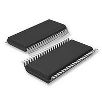
LV8741V-TLM-E ON Semiconductor, LV8741V-TLM-E Datasheet - Page 11

LV8741V-TLM-E
Manufacturer Part Number
LV8741V-TLM-E
Description
Motor / Motion / Ignition Controllers & Drivers STEPPING MOTOR
Manufacturer
ON Semiconductor
Datasheet
1.LV8741V-TLM-E.pdf
(25 pages)
Specifications of LV8741V-TLM-E
Motor Type
DC
No. Of Outputs
2
Driver Case Style
SSOP
No. Of Pins
44
Operating Temperature Range
-20°C To +85°C
Svhc
No SVHC (20-Jun-2011)
Base Number
8741
Rohs Compliant
Yes
Lead Free Status / Rohs Status
Details
Available stocks
Company
Part Number
Manufacturer
Quantity
Price
Company:
Part Number:
LV8741V-TLM-E
Manufacturer:
ON Semiconductor
Quantity:
1 550
Part Number:
LV8741V-TLM-E
Manufacturer:
SANYO/三洋
Quantity:
20 000
Input Pin Function
(1) Chip enable function
(2) Drive mode switching pin function
STM mode (DM = Low or Open)
(1) STEP pin function
(2) Excitation mode setting function
(3) Constant-current control reference voltage setting function
Set current value calculation method
This IC is switched between standby and operating mode by setting the ST pin. In standby mode, the IC is set to
power-save mode and all logic is reset. In addition, the internal regulator circuit and charge pump circuit do not
operate in standby mode.
The IC drive mode is switched by setting the DM pin. In STM mode, stepping motor channel 1 can be controlled by
the CLK-IN input. In DCM mode, DC motor channel 2 or stepping motor channel 1 can be controlled by parallel
input. Stepping motor control using parallel input is 2-phase or 1-2 phase full torque.
This is the initial position of each excitation mode in the initial state after power-on and when the counter is reset.
The voltage input to the VREF pin can be switched to four-step settings as the reference voltage for setting the output current. This is effective for
reducing power consumption when motor holding current is supplied.
The reference voltage is set by the voltage applied to the VREF pin and the two inputs ATT1 and ATT2. The output
current (output current at a constant-current drive current ratio of 100%) can be set from this reference voltage and the
RF resistance value.
(Example) When VREF = 1.5V, setting current ratio = 100% [(ATT1, ATT2) = (Low, Low)] and RF resistor = 0.5Ω,
the following output current flows :
I OUT = (VREF/3 × Voltage setting ratio)/RF resistor
I OUT = 1.5V/3 × 100%/0.5Ω = 1A
ATT1
High
High
MD1
Low
High
High
High
High
Low
Low
Low
Low
Low or Open
ST
Low or Open
High
High
ST
DM
Input
ATT2
STP
MD2
High
High
High
High
Low
Low
Low
Low
*
Operating mode
Standby mode
Drive mode
DCM mode
STM mode
Mode
2 phase excitation
1-2 phase excitation (full torque)
1-2 phase excitation
W1-2 phase excitation
Excitation mode
Current setting reference voltage
Excitation step proceeds
Excitation step is kept
Operating mode
Standby mode
VREF/3×100%
VREF/3×67%
VREF/3×50%
VREF/3×33%
LV8741V
Internal regulator
Operating
Standby
DC motor channel 2 or stepping motor channel 1 (parallel)
Channel 1
Stepping motor channel 1 (CLK-IN)
100%
100%
100%
100%
Charge pump
Operating
Application
Initial position
Standby
Channel 2
-100%
0%
0%
0%
No.A0814-11/25


