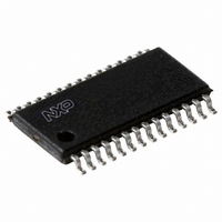
PCA9558PW,118 NXP Semiconductors, PCA9558PW,118 Datasheet - Page 18

PCA9558PW,118
Manufacturer Part Number
PCA9558PW,118
Description
IC I2C SMBUS 8BIT I/O 28TSSOP
Manufacturer
NXP Semiconductors
Datasheet
1.PCA9558PW112.pdf
(27 pages)
Specifications of PCA9558PW,118
Package / Case
28-TSSOP
Applications
PC's, PDA's
Interface
I²C
Voltage - Supply
3 V ~ 3.6 V
Mounting Type
Surface Mount
Logic Family
PCA9558
Number Of Lines (input / Output)
8.0 / 8.0
Propagation Delay Time
21 ns
Operating Supply Voltage
3 V to 3.6 V
Operating Temperature Range
0 C to + 70 C
Input Voltage
5 V
Logic Type
I2C, SMBus
Maximum Clock Frequency
400 KHz
Mounting Style
SMD/SMT
Number Of Input Lines
8.0
Number Of Output Lines
8.0
Output Voltage
5 V
Lead Free Status / RoHS Status
Lead free / RoHS Compliant
Lead Free Status / RoHS Status
Lead free / RoHS Compliant, Lead free / RoHS Compliant
Other names
935269433118
PCA9558PW-T
PCA9558PW-T
PCA9558PW-T
PCA9558PW-T
NXP Semiconductors
12. Dynamic characteristics
Table 12.
[1]
[2]
PCA9558_4
Product data sheet
Symbol
MUX_INx to MUX_OUTx
t
t
MUX_SELECT to MUX_OUTx
t
t
MUX_OUT_LOW to NON_MUXED_OUT
t
t
MUX_OUT_LOW to MUX_OUTx
t
t
t
t
C
I
f
t
t
t
t
t
t
t
t
t
t
t
C
T
PLH
PHL
PLH
PHL
PLH
PHL
PLH
PHL
r
f
2
SCL
BUF
HD;STA
LOW
HIGH
SU;STA
HD;DAT
SU;DAT
SP
SU;STO
r
f
cy(W)
C-bus
L
b
After this period, the first clock pulse is generated.
Write cycle time can only be measured indirectly during the write cycle. During this time, the device will not acknowledge its I
address.
Dynamic characteristics
Parameter
LOW to HIGH propagation delay
HIGH to LOW propagation delay
LOW to HIGH propagation delay
HIGH to LOW propagation delay
LOW to HIGH propagation delay
HIGH to LOW propagation delay
LOW to HIGH propagation delay
HIGH to LOW propagation delay
rise time
fall time
load capacitance
SCL clock frequency
bus free time between a STOP and START
condition
hold time (repeated) START condition
LOW period of the SCL clock
HIGH period of the SCL clock
set-up time for a repeated START condition
data hold time
data set-up time
pulse width of spikes that must be
suppressed by the input filter
set-up time for STOP condition
rise time of both SDA and SCL signals
fall time of both SDA and SCL signals
capacitive load for each bus line
write cycle time
Rev. 04 — 14 April 2009
Conditions
output
output
test load on outputs
10 pF to 400 pF bus
10 pF to 400 pF bus
[1]
[2]
Min
-
-
-
-
-
-
-
-
1.0
1.0
-
10
1.3
600
1.3
600
600
0
100
0
600
20
20
-
-
8-bit I
2
Typ
21
7
20
8
20
8
20
7.0
-
-
-
-
-
-
-
-
-
-
-
-
-
-
-
-
15
C-bus/SMBus I/O port
PCA9558
© NXP B.V. 2009. All rights reserved.
Max
28
10
28
12
26
15
28
15
10
5
10
400
-
-
-
10
50
10
300
300
400
-
12
32
100
2
C-bus
18 of 27
Unit
ns
ns
ns
ns
ns
ns
ns
ns
ns/V
ns/V
pF
kHz
ns
ns
ns
ns
ns
ns
ns
ns
ns
pF
ms
s
s


