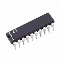
LTC1061ACN Linear Technology, LTC1061ACN Datasheet - Page 3

LTC1061ACN
Manufacturer Part Number
LTC1061ACN
Description
IC FILTER BUILDNG BLK TRPL 20DIP
Manufacturer
Linear Technology
Datasheet
1.LTC1061CNPBF.pdf
(16 pages)
Specifications of LTC1061ACN
Filter Type
Universal Switched Capacitor
Frequency - Cutoff Or Center
35kHz
Number Of Filters
3
Max-order
6th
Voltage - Supply
4.74 V ~ 16 V, ±2.37 V ~ 8 V
Mounting Type
Through Hole
Package / Case
20-DIP (0.300", 7.62mm)
Lead Free Status / RoHS Status
Contains lead / RoHS non-compliant
Available stocks
Company
Part Number
Manufacturer
Quantity
Price
Company:
Part Number:
LTC1061ACN#PBF
Manufacturer:
LT
Quantity:
1 001
ELECTRICAL CHARACTERISTICS
operating temperature range, otherwise specifications are at V
(Complete Filter) The
at V
(Internal Op Amps) The
are at T
Supply Voltage Range
Voltage Swings
Output Short-Circuit Current
DC Open-Loop Gain
GBW Product
Slew Rate
Note 1: Absolute Maximum Ratings are those values beyond which the life
of a device may be impaired.
PARAMETER
f
Q Temperature Coefficient
DC Offset Voltage
Clock Feedthrough
Maximum Clock Frequency
Power Supply Current
Center Frequency Range, f
Input Frequency Range
Clock-to-Center Frequency Ratio
Q Accuracy
Maximum Clock Frequency
Power Supply Current
O
Temperature Coefficient
LTC1061A
LTC1061
LTC1061, LTC1061A
Source/Sink
V
V
V
V
V
LTC1061A
LTC1061
LTC1061A
LTC1061
LTC1061A
LTC1061
S
OS1
OS2
OS2
OS3
OS3
= ±2.37V, T
, Figure 23
, LTC1061CN, ACN/LTC1061CS
, LTC1061CN, ACN/LTC1061CS
A
= 25°C, unless otherwise specified.
A
= 25°C, unless otherwise specified.
●
O
●
denotes the specifications which apply over the full operating temperature range, otherwise specifications are
denotes the specifications which apply over the full operating temperature range, otherwise specifications
CONDITIONS
Mode 1, 50:1, f
Mode 1, 100:1, f
Mode 3, f
f
f
f
f
f
Mode 1, Q < 5, V
f
f
50:1, f
Sides A, B: Mode 1
Side C, Mode 3, 250kHz
100:1, f
Sides A, B: Mode 1
Side C: Mode 3
Same as Above
V
V
V
V
V
V
CLK
CLK
CLK
CLK
CLK
O
O
S
S
S
S
S
S
× Q ≤ 120kHz, Mode 1, 50:1
× Q ≤ 120kHz, Mode 3, 50:1
= ±5V, R
= ±5V, R
= ±5V
= ±5V, R
= ±5V
= ±5V
= 250kHz, 50:1
= 500kHz, 100:1
= 250kHz, 50:1
= 500kHz, 100:1
< 1MHz
CLK
CLK
CLK
= 250kHz, Q = 10
= 500kHz, Q = 10
L
L
L
< 500kHz
= 5k (Pins 1,2,13,14,19,20)
= 3.5k (Pins 3,12,18)
= 5k
CLK
CLK
S
≥ ±5
(Complete Filter) The
< 300kHz
< 500kHz
S
= ±5V, T
A
= 25°C, T
●
denotes the specifications which apply over the full
●
●
●
●
●
●
●
2
L clock input level, unless otherwise specified.
±2.37
±4.0
±3.8
±3.6
MIN
6
100 ±0.6%
100 ±1.0%
0.1– 12k
0.1– 10k
50 ±0.6%
50 ±1.0%
0 – 20k
±4.2
±4.2
40/3
TYP
700
0.4
2.5
±1
±5
±5
±2
±3
4.5
80
3
7
2
3
6
3
6
8
20/25
40/50
MAX
±9
15
30
60
11
15
6
LTC1061
ppm/°C
ppm/°C
ppm/°C
mV
UNITS
1061fe
3
MHz
V/µs
MHz
RMS
kHz
mA
mV
mV
mV
mV
mV
mA
mA
mA
dB
Hz
Hz
Hz
%
%
V
V
V
V


