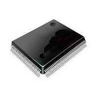
ST92F120V1Q7 STMicroelectronics, ST92F120V1Q7 Datasheet - Page 45

ST92F120V1Q7
Manufacturer Part Number
ST92F120V1Q7
Description
Microcontrollers (MCU) Flash 128K SPI/I2C
Manufacturer
STMicroelectronics
Datasheet
1.ST92F120V9Q7.pdf
(325 pages)
Specifications of ST92F120V1Q7
Data Bus Width
8 bit, 16 bit
Program Memory Type
Flash
Program Memory Size
128 KB
Data Ram Size
4 KB
Interface Type
I2C, SPI
Maximum Clock Frequency
24 MHz
Number Of Programmable I/os
77
Number Of Timers
5
Maximum Operating Temperature
+ 105 C
Mounting Style
SMD/SMT
Package / Case
PQFP-100
Minimum Operating Temperature
- 40 C
On-chip Adc
8 bit, 16 Channel
Lead Free Status / Rohs Status
No
Available stocks
Company
Part Number
Manufacturer
Quantity
Price
Company:
Part Number:
ST92F120V1Q7
Manufacturer:
ST
Quantity:
6 765
Part Number:
ST92F120V1Q7
Manufacturer:
ST
Quantity:
20 000
Part Number:
ST92F120V1Q7C
Manufacturer:
ST
Quantity:
20 000
Company:
Part Number:
ST92F120V1Q7DTR
Manufacturer:
MAXIM
Quantity:
2 854
- Current page: 45 of 325
- Download datasheet (3Mb)
REGISTER DESCRIPTION (Cont’d)
3.3.2 Status Registers
During a Flash or an EEPROM write operation any
attempt to read the memory under modification will
output invalid data (FFh equivalent to a NOP in-
struction). This means that the Flash memory is
not fetchable when a write operation is active: the
write operation commands must be given from an-
other memory (EEPROM, internal RAM, or exter-
nal memory).
Two Status Registers (FESR[1:0] are available to
check the status of the current write operation in
Flash and EEPROM memories.
FLASH & EEPROM STATUS REGISTER 0
(FESR0)
Address: 224002h -Read/Write
Reset value: 0000 0000 (00h)
Bit 7 = FEERR: Flash or EEPROM write ERRor
(Read/Write).
This bit is set by hardware when an error occurs
during a Flash or an EEPROM write operation. It
must be cleared by software.
0: Write OK
1: Flash or EEPROM write error
Bits 6:0 = FESS[6:0]. Flash and EEPROM Status
Sector 6-0 (Read Only).
These bits are set by hardware and give the status
of the 7 Flash and EEPROM sectors (TF, E1, E0,
F3, F2, F1, F0). The meaning of FESSx bit for sec-
tor x is given by the following table:
Table 9. FESSx bit Values
FEER
FEERR
R
7
1
0
FESS
6
6
FBUSY
EBUSY
FESS
1
5
5
-
FESS
4
4
FSUSP
FESS
-
-
3
3
FESS
on-going in sec-
2
2
Write operation
Write Error in
FESSx=1
meaning
Sector x
FESS
tor x
1
1
ST92F120 - SINGLE VOLTAGE FLASH & EEPROM
FESS
0
0
Table 9. FESSx bit Values
FLASH & EEPROM STATUS REGISTER 1
(FESR1)
Address: 224003h -Read Only
Reset value: 0000 0000 (00h)
Bit 7 = ERER. Erase error (Read Only).
This bit is set by hardware when an Erase error oc-
curs during a Flash or an EEPROM write opera-
tion. This error is due to a real failure of a Flash
cell, that can not be erased anymore. This kind of
error is fatal and the sector where it occurred must
be discarded (if it was in one of the EEPROM sec-
tors, the hardware emulation can not be used any-
more). This bit is automatically cleared when bit
FEERR of the FESR0 register is cleared by soft-
ware.
0: Erase OK
1: Erase error
Bit 6 = PGER. Program error (Read Only).
This bit is automatically set when a Program error
occurs during a Flash or an EEPROM write opera-
tion. This error is due to a real failure of a Flash
cell, that can not be programmed anymore. The
byte where this error occurred must be discarded
(if it was in the EEPROM memory, the byte must
be reprogrammed to FFh and then discarded, to
avoid the error occurring again when that byte is
internally moved). This bit is automatically cleared
when bit FEERR of the FESR0 register is cleared
by software.
0: Program OK
1: Flash or EEPROM Programming error
ERER PGER
FEERR
7
0
0
6
EBUSY
FBUSY
SWE
R
0
0
5
4
FSUSP
1
0
3
2
Suspended in
Sector Erase
Don’t care
FESSx=1
meaning
sector x
1
45/324
0
9
Related parts for ST92F120V1Q7
Image
Part Number
Description
Manufacturer
Datasheet
Request
R

Part Number:
Description:
8/16-bit Flash Mcu Family With Ram, Eeprom And J1850 Blpd
Manufacturer:
STMicroelectronics
Datasheet:

Part Number:
Description:
STMicroelectronics [RIPPLE-CARRY BINARY COUNTER/DIVIDERS]
Manufacturer:
STMicroelectronics
Datasheet:

Part Number:
Description:
STMicroelectronics [LIQUID-CRYSTAL DISPLAY DRIVERS]
Manufacturer:
STMicroelectronics
Datasheet:

Part Number:
Description:
BOARD EVAL FOR MEMS SENSORS
Manufacturer:
STMicroelectronics
Datasheet:

Part Number:
Description:
NPN TRANSISTOR POWER MODULE
Manufacturer:
STMicroelectronics
Datasheet:

Part Number:
Description:
TURBOSWITCH ULTRA-FAST HIGH VOLTAGE DIODE
Manufacturer:
STMicroelectronics
Datasheet:

Part Number:
Description:
Manufacturer:
STMicroelectronics
Datasheet:

Part Number:
Description:
DIODE / SCR MODULE
Manufacturer:
STMicroelectronics
Datasheet:

Part Number:
Description:
DIODE / SCR MODULE
Manufacturer:
STMicroelectronics
Datasheet:

Part Number:
Description:
Search -----> STE16N100
Manufacturer:
STMicroelectronics
Datasheet:

Part Number:
Description:
Search ---> STE53NA50
Manufacturer:
STMicroelectronics
Datasheet:

Part Number:
Description:
NPN Transistor Power Module
Manufacturer:
STMicroelectronics
Datasheet:


