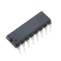
MC44603P ON Semiconductor, MC44603P Datasheet - Page 5

MC44603P
Manufacturer Part Number
MC44603P
Description
Other Power Management Voltage/Current PWM
Manufacturer
ON Semiconductor
Type
PWM Mode Controllerr
Datasheet
1.MC44603DWR2.pdf
(24 pages)
Specifications of MC44603P
Input Voltage Range
18 V
Mounting Style
Through Hole
Package / Case
PDIP-16
Lead Free Status / Rohs Status
Lead free / RoHS Compliant
Available stocks
Company
Part Number
Manufacturer
Quantity
Price
Part Number:
MC44603P
Manufacturer:
MOTOROLA/摩托罗拉
Quantity:
20 000
Company:
Part Number:
MC44603P2
Manufacturer:
ON
Quantity:
9 800
ELECTRICAL CHARACTERISTICS
25°C, for min/max values T
OSCILLATOR AND SYNCHRONIZATION SECTION
UNDERVOLTAGE LOCKOUT SECTION
DEMAGNETIZATION DETECTION SECTION (Note 8)
SOFT−START SECTION (Note 10)
2. Adjust V
3. Low duty cycle pulse techniques are used during test to maintain junction temperature as close to ambient as possible.
4. V
5. Standby is disabled for V
6. If not used, Synchronization input must be connected to Ground.
7. Synchronization Pulse Width must be shorter than t
8. This function can be inhibited by connecting Pin 8 to GND. This allows a continuous current mode operation.
9. This function can be inhibited by connecting Pin 5 to V
10. The MC44603A can be shut down by connecting the Soft−Start pin (Pin 11) to Ground.
Oscillator Voltage Swing (Peak−to−Peak)
Ratio Charge Current/Reference Current
Fixed Maximum Duty Cycle = I
Ratio Standby Discharge Current versus I
V
Frequency in Standby Mode (R
Current Range
Synchronization Input Threshold Voltage (Note 6)
Synchronization Input Current
Minimum Synchronization Pulse Width (Note 7)
Startup Threshold
Output Disable Voltage After Threshold Turn−On (UVLO 1)
Reference Disable Voltage After Threshold Turn−On (UVLO 2)
Demagnetization Detect Input
Negative Clamp Level (I
Positive Clamp Level (I
Ratio Charge Current/I
Discharge Current (V
Clamp Level
R F Stby
T
T
T
T
T
T
Demagnetization Comparator Threshold (V
Propagation Delay (Input to Output, Low to High)
Input Bias Current (V
T
T
A
A
A
A
A
A
A
A
C
= 0° to +70°C (V
= −25° to +85°C
= 0° to +70°C
= −25° to +85°C (Note 8)
= 0° to +70°C
= −25° to +85°C
= 0° to +70°C
= −25° to +85°C
must be greater than 5.0 V.
(I
R F Stby
CC
above the startup threshold before setting to 12 V.
= 100 mA)
soft−start
CT
ref
demag
demag
demag
= 2.0 V)
A
R P Stby
= −25° to +85°C (Note 3), unless otherwise noted.)
Characteristic
= 2.0 mA)
= 1.0 V)
= 65 mV)
= −2.0 mA)
discharge
F Stby
< 25 mV typical.
(Pin 15) = 25 kW)
/(I
(continued) (V
discharge
R F Stby
Pin 9
+ I
(Note 5)
Decreasing)
charge
OSC
CC
CC
http://onsemi.com
)
and V
= 1/f
.
OSC
C
= 12 V, (Note 2), R
.
5
I
I
V
disch−Stby
I
V
V
I
I
charge
V
V
Symbol
I
I
ss(ch)
V
demag−lb
discharge
I
C
V
demag−th
C
R F Stby
R F Stby
Sync−in
OSC(pp)
R F Stby
V
V
disable1
disable2
F
t
stup−th
ss(CL)
L(neg)
L(pos)
Sync
inthH
Stby
inthL
D
−
ref
/I
/I
ref
ref
= 10 kW, C
/
0.375
−200
1.65
0.37
0.46
0.43
0.45
−5.0
13.6
−0.5
0.37
0.36
Min
2.4
3.2
8.6
8.3
7.0
1.5
2.2
78
18
50
−
−
−
−
T
= 820 pF, for typical values T
−0.38
0.53
14.5
0.25
0.72
Typ
1.8
0.4
2.5
3.7
0.7
9.0
7.5
0.4
5.0
2.4
80
21
65
−
−
−
−
−
−
−
−
0.425
Max
1.95
0.43
0.63
15.4
0.43
0.44
−50
0.6
2.6
4.3
0.9
0.5
9.4
9.6
8.0
2.6
82
24
80
0
−
−
−
−
−
A
Unit
kHz
=
mV
mA
mA
mA
mA
ms
ms
%
V
V
V
V
V
V
V
V
V
−
−
−


