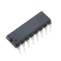
MC44603P ON Semiconductor, MC44603P Datasheet - Page 19

MC44603P
Manufacturer Part Number
MC44603P
Description
Other Power Management Voltage/Current PWM
Manufacturer
ON Semiconductor
Type
PWM Mode Controllerr
Datasheet
1.MC44603DWR2.pdf
(24 pages)
Specifications of MC44603P
Input Voltage Range
18 V
Mounting Style
Through Hole
Package / Case
PDIP-16
Lead Free Status / Rohs Status
Lead free / RoHS Compliant
Available stocks
Company
Part Number
Manufacturer
Quantity
Price
Part Number:
MC44603P
Manufacturer:
MOTOROLA/摩托罗拉
Quantity:
20 000
Company:
Part Number:
MC44603P2
Manufacturer:
ON
Quantity:
9 800
is close to the threshold value, a hysteresis that is
proportional to V
V
When the standby comparator output is high, a second
current source (0.6 x I
graphically in Figure 42.
levels:
P
Maximum Duty Cycle and Soft−Start Control
80% by utilizing the D
depicted in Figure 43, the Pin 11 voltage is compared to the
oscillator sawtooth.
thL
CS
In order to prevent undesired mode switching when power
Finally, the standby mode function can be shown
This curve shows that there are two power threshold
− the low one:
− the high one:
Maximum duty cycle can be limited to values less than
P
P
fixed by V
threshold level that is equal to [2.5 x (V
P
Soft-Start
thH
Capacitor
thL
in
Figure 42. Dynamic Mode Change
11
Figure 43. D
[(V
P thH + (2.5) 2 x P thL x
P thH + 6.25 x P thL x
R P Stby
D
Z
R P Stby
R P Stby
V
2.4 V
ref
ref
)/3]
0.4 I
V
) is connected to Pin 12.
OSC
Working
is incorporated creating a second
Normal
max
C
max
ref
Dmax
and Soft−Start
Standby
2.5 x [(V
and soft−start control. As
Oscillator
Control
Output
R P Stby
D
f Stby
max
f Stby
f S
f S
)/3]
f
S
f
Stby
Output
Drive
R P Stby
1
V
http://onsemi.com
CS
)/3].
19
voltage can easily be set by connecting a resistor to this pin.
from 0 to its maximum value progressively (refer to
Figure 45), thereby, implementing a soft−start. The
soft−start capacitor is discharged internally when the V
(Pin 1) voltage drops below 9.0 V.
internal zener diode clamps the Pin 11 voltage to a value V
that is higher than the oscillator peak value, disabling
soft−start and maximum duty cycle limitation.
Foldback
(Pin 5) can be used to reduce the maximum V
providing foldback protection. The foldback arrangement is
a programmable peak current limitation.
current becomes higher and V
maximum value (normally, V
unable to supply enough energy to maintain the output
voltages in regulation. Consequently, the decreasing output
can be applied to Pin 5, in order to limit the maximum peak
current. In this way, the well known foldback characteristic
can be obtained (refer to Figure 46).
Pin 11
Voltage
Using the internal current source (0.4 I
If a capacitor is connected to Pin 11, the voltage increases
If no external component is connected to Pin 11, an
As depicted in Figures 33 and 49, the foldback input
If the output load is increased, the required converter peak
Then, if the output load keeps on increasing, the system is
D
RI
max
Figure 45. Different Possible Uses of Pin 11
R Connected to Pin 11
I = 0.4 I
Figure 44. Maximum Duty Cycle Control
ref
V
Z
CS
CS max
C
increases until it reaches its
= 1.0 V).
V
RI
Z
ref
), the Pin 11
C // R
CS
t = RC
Pin 11
V
(Pin 10)
CT
value,
CC
Z


