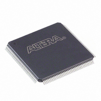
EPF6016TC144-3 Altera, EPF6016TC144-3 Datasheet - Page 50

EPF6016TC144-3
Manufacturer Part Number
EPF6016TC144-3
Description
IC FLEX 6000 FPGA 16K 144-TQFP
Manufacturer
Altera
Series
FLEX 6000r
Datasheet
1.EPF6010ATC100-3N.pdf
(52 pages)
Specifications of EPF6016TC144-3
Number Of Logic Elements/cells
1320
Number Of Labs/clbs
132
Number Of I /o
117
Number Of Gates
16000
Voltage - Supply
4.75 V ~ 5.25 V
Mounting Type
Surface Mount
Operating Temperature
0°C ~ 85°C
Package / Case
144-TQFP, 144-VQFP
Lead Free Status / RoHS Status
Contains lead / RoHS non-compliant
Total Ram Bits
-
Other names
544-1282
Available stocks
Company
Part Number
Manufacturer
Quantity
Price
Company:
Part Number:
EPF6016TC144-3
Manufacturer:
ALTERA
Quantity:
48
Company:
Part Number:
EPF6016TC144-3
Manufacturer:
SANYO
Quantity:
47
Company:
Part Number:
EPF6016TC144-3
Manufacturer:
ALTERA
Quantity:
1 066
Part Number:
EPF6016TC144-3
Manufacturer:
ALTERA/阿尔特拉
Quantity:
20 000
Company:
Part Number:
EPF6016TC144-3N
Manufacturer:
ALTERA42
Quantity:
1 341
Part Number:
EPF6016TC144-3N
Manufacturer:
ALTERA/阿尔特拉
Quantity:
20 000
FLEX 6000 Programmable Logic Device Family Data Sheet
50
Configuration device
Passive serial (PS)
Passive serial asynchronous
(PSA)
Table 40. Configuration Schemes
Configuration Scheme
Operating Modes
The FLEX 6000 architecture uses SRAM configuration elements that
require configuration data to be loaded every time the circuit powers
up. This process of physically loading the SRAM data into a FLEX
6000 device is known as configuration. During initialization—a
process that occurs immediately after configuration—the device
resets registers, enables I/O pins, and begins to operate as a logic
device. The I/O pins are tri-stated during power-up, and before and
during configuration. The configuration and initialization processes
of a device are referred to as command mode; normal device operation
is called user mode.
SRAM configuration elements allow FLEX 6000 devices to be
reconfigured in-circuit by loading new configuration data into the
device. Real-time reconfiguration is performed by forcing the device
into command mode with a device pin, loading different
configuration data, reinitializing the device, and resuming user-
mode operation. The entire reconfiguration process requires less
than 100 ms and is used to dynamically reconfigure an entire system.
Also, in-field system upgrades can be performed by distributing new
configuration files.
Configuration Schemes
The configuration data for a FLEX 6000 device can be loaded with
one of three configuration schemes, which is chosen on the basis of
the target application. An EPC1 or EPC1441 configuration device or
intelligent controller can be used to control the configuration of a
FLEX 6000 device, allowing automatic configuration on system
power-up.
Multiple FLEX 6000 devices can be configured in any of the three
configuration schemes by connecting the configuration enable input
(nCE) and configuration enable output (nCEO) pins on each device.
Table 40
shows the data sources for each configuration scheme.
EPC1 or EPC1441 configuration device
BitBlaster
download cables, or serial data source
BitBlaster, ByteBlasterMV, or MasterBlaster
download cables, or serial data source
TM
, ByteBlasterMV
Data Source
TM
, or MasterBlaster
Altera Corporation
TM


