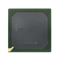
PRIXP425BC 869083 Intel, PRIXP425BC 869083 Datasheet - Page 25

PRIXP425BC 869083
Manufacturer Part Number
PRIXP425BC 869083
Description
Manufacturer
Intel
Datasheet
1.PRIXP425BC_869083.pdf
(130 pages)
Specifications of PRIXP425BC 869083
Core Operating Frequency
400MHz
Package Type
BGA
Pin Count
492
Mounting
Surface Mount
Operating Temperature (max)
70C
Operating Temperature (min)
0C
Operating Temperature Classification
Commercial
Lead Free Status / Rohs Status
Compliant
- Current page: 25 of 130
- Download datasheet (3Mb)
Intel
2.1.9
2.1.10
2.1.11
2.1.12
August 2006
Document Number: 252479-006US
®
IXP42X product line and IXC1100 control plane processors
The expansion bus interface is an asynchronous interface to externally connected
chips. However, a clock must be supplied to the IXP42X product line and IXC1100
control plane processors’ expansion bus interface for the interface to operate. This
clock can be driven from GPIO 15 or an external source. The maximum clock rate that
the expansion bus interface can accept is 66.66 MHz.
At the de-assertion of reset, the 24-bit address bus is used to capture configuration
information from the levels that are applied to the pins at this time. External pull-up/
pull-down resistors are used to tie the signals to particular logic levels. For additional
details, refer to Section 8 (Expansion Bus Controller) of the Intel
of Network Processors and IXC1100 Control Plane Processor Developer’s Manual.)
High-Speed, Serial Interfaces
The high-speed, serial interfaces are six-signal interfaces that support serial transfer
speeds from 512 KHz to 8.192 MHz, for some models of the IXP42X product line and
IXC1100 control plane processors. (See
Each interface allows direct connection of up to four T1/E1 framers and CODEC/SLICs
to the IXP42X product line and IXC1100 control plane processors. The high-speed,
serial interfaces are capable of supporting various protocols, based on the
implementation of the code developed for the network processor engine. For a list of
supported protocols, see the Intel
High-Speed and Console UARTs
The UART interfaces are 16550-compliant UARTs with the exception of transmit and
receive buffers. Transmit and receive buffers are 64 bytes-deep versus the 16 bytes
required by the 16550 UART specification.
The interface can be configured to support speeds from 1,200 baud to 921 Kbaud. The
interface support configurations of:
The request-to-send (RTS_N) and clear-to-send (CTS_N) modem control signals also
are available with the interface for hardware flow control.
GPIO
16 GPIO pins are supported by the IXP42X product line and IXC1100 control plane
processors. GPIO pins 0 through 15 can be configured to be general-purpose input or
general-purpose output. Additionally, GPIO pins 0 through 12 can be configured to be
an interrupt input.
GPIO Pin 14 and GPIO 15 can also be configured as a clock output. The output-clock
configuration can be set at various speeds, up to 33.33 MHz, with various duty cycles.
GPIO Pin 14 is configured as an input, upon reset. GPIO Pin 15 is configured as an
output, upon reset. GPIO Pin 15 can be used to clock the expansion interface, after
reset.
Internal Bus Performance Monitoring Unit (IBPMU)
The IXP42X product line and IXC1100 control plane processors consists of seven 27-bit
counters that may be used to capture predefined durations or occurrence events on the
North AHB, South AHB, or SDRAM controller page hits/misses.
• Five, six, seven, or eight data-bit transfers
• One or two stop bits
• Even, odd, or no parity
Intel
®
IXP42X Product Line of Network Processors and IXC1100 Control Plane Processor
®
IXP400 Software Programmer’s Guide.
Table 4 on page
21.)
®
IXP42X Product Line
Datasheet
25
Related parts for PRIXP425BC 869083
Image
Part Number
Description
Manufacturer
Datasheet
Request
R

Part Number:
Description:
IC NETWRK PROCESSR 400MHZ 492BGA
Manufacturer:
Intel
Datasheet:

Part Number:
Description:
Microprocessor: Intel Celeron M Processor 320 and Ultra Low Voltage Intel Celeron M Processor at 600MHz
Manufacturer:
Intel Corporation

Part Number:
Description:
Intel 82550 Fast Ethernet Multifunction PCI/CardBus Controller
Manufacturer:
Intel Corporation
Datasheet:

Part Number:
Description:
Intel StrataFlash memory 32 Mbit. Access speed 120 ns
Manufacturer:
Intel Corporation
Datasheet:

Part Number:
Description:
Intel StrataFlash memory 32 Mbit. Access speed 120 ns
Manufacturer:
Intel Corporation
Datasheet:

Part Number:
Description:
Intel StrataFlash memory 64 Mbit. Access speed 150 ns
Manufacturer:
Intel Corporation
Datasheet:

Part Number:
Description:
Intel StrataFlash memory 32 Mbit. Access speed 100 ns
Manufacturer:
Intel Corporation
Datasheet:

Part Number:
Description:
DA28F640J5A-1505 Volt Intel StrataFlash Memory
Manufacturer:
Intel Corporation
Datasheet:

Part Number:
Description:
5 Volt Intel StrataFlash?? Memory
Manufacturer:
Intel Corporation
Datasheet:

Part Number:
Description:
5 Volt Intel StrataFlash?? Memory
Manufacturer:
Intel Corporation

Part Number:
Description:
Intel 6300ESB I/O Controller Hub
Manufacturer:
Intel Corporation
Datasheet:

Part Number:
Description:
Intel 82801DB I/O Controller Hub (ICH4), Pb-Free SLI
Manufacturer:
Intel Corporation
Datasheet:

Part Number:
Description:
Intel 82801FB I/O Controller Hub (ICH6)
Manufacturer:
Intel Corporation
Datasheet:

Part Number:
Description:
Intel Strataflash Memory28F128J3 28F640J3 28F320J3
Manufacturer:
Intel Corporation
Datasheet:


