ADC12048CIV/NOPB National Semiconductor, ADC12048CIV/NOPB Datasheet - Page 23
ADC12048CIV/NOPB
Manufacturer Part Number
ADC12048CIV/NOPB
Description
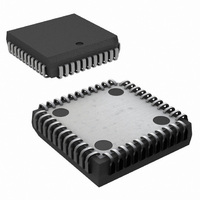
IC ADC 12BIT+SIGN 8-CH 44-PLCC
Manufacturer
National Semiconductor
Datasheet
1.ADC12048CIVNOPB.pdf
(32 pages)
Specifications of ADC12048CIV/NOPB
Number Of Bits
12
Sampling Rate (per Second)
216k
Data Interface
Parallel
Number Of Converters
1
Power Dissipation (max)
875mW
Voltage Supply Source
Analog and Digital
Operating Temperature
-40°C ~ 85°C
Mounting Type
Surface Mount
Package / Case
44-LCC (J-Lead)
Leaded Process Compatible
Yes
Rohs Compliant
Yes
Peak Reflow Compatible (260 C)
Yes
Lead Free Status / RoHS Status
Lead free / RoHS Compliant
Other names
*ADC12048CIV
*ADC12048CIV/NOPB
ADC12048CIV
*ADC12048CIV/NOPB
ADC12048CIV
Available stocks
Company
Part Number
Manufacturer
Quantity
Price
Company:

Part Number:
ADC12048CIV/NOPB
Manufacturer:
Texas Instruments
Quantity:
10 000


Register Bit Description
CONFIGURATION REGISTER (Write Only)
This is a 13-bit write-only register that is used to program the
functionality of the ADC12048. All data written to the
ADC12048 will always go to this register only. The contents
Power on State: 0100Hex
b
MUX. They select which input channels of the MUX will
b
quistion times in SYNC-OUT mode. (Refer to Selectable
b
results will be limited to positive values only and any nega-
tive conversion results will appear as a code of zero in the
Data register. The SE bit is cleared at power-up.
b
(BW bit b
(BW bit b
of the Configuration Register in 8-bit mode. When this bit is
set and bit b
will program the upper byte of the Configuration register. The
HB bit will automatically be cleared when data is written to
the upper byte of the Configuration register, allowing the
lower byte to be accessed with the next write. The HB bit is
cleared at power-up.
3
5
6
7
–b
–b
: When the Single-Ended bit (SE bit) is set, conversion
: The High Byte bit (HB) is meaningful only in 8-bit mode
MSB
0
4
: The MUX ADDRESS bits configure the analog input
: The ACQ TIME bits select one of four possible ac-
BW
b
12
12
12
= “0”) and is a don’t care condition in 13-bit mode
= “1”). This bit is used to access the upper byte
12
b
= 0, the next byte written to the ADC12048
11
COMMAND FIELD
b
0
0
0
0
0
0
0
0
1
1
1
1
1
1
1
1
b
3
10
b
9
b
0
0
0
0
1
1
1
1
0
0
0
0
1
1
1
1
2
SYNC
b
TABLE 1. MUX Channel Assignment
8
b
b
0
0
1
1
0
0
1
1
0
0
1
1
0
0
1
1
0
0
1
1
5
HB
1
b
7
b
0
1
0
1
SE
4
b
23
6
b
0
1
0
1
0
1
0
1
0
1
0
1
0
1
0
1
0
of this register cannot be read.
connect to the MUXOUT+ and MUXOUT− pins. (Refer to the
MUX section for more details on the MUX.) Power-up value
is 0000.
Acquisition Time section.)
b
is programmed as an input and the converter is in synchro-
nous mode. In this mode a rising edge on the SYNC pin
causes the ADC to hold the input signal and begin a conver-
sion. When b
output and the converter is in an asynchronous mode. In this
mode the signal at the SYNC pin indicates the status of the
converter. The SYNC pin is high when a conversion is taking
place. The SYNC bit is set at power-up.
b
operation of the ADC12048. Power-up value is 000. (See
(Note 22))
8
11
Clocks
: The SYNC bit. When the SYNC bit is set, the SYNC pin
–b
b
ACQ TIME
5
9
: The command field. These bits select the mode of
MUXOUT+
15
47
79
9
CH0
CH1
CH2
CH3
CH4
CH5
CH6
CH7
CH0
CH1
CH2
CH3
CH4
CH5
CH6
CH7
15
b
4
cleared, the SYNC pin is programmed as an
b
3
MUXOUT−
MUX ADDRESS
COM
COM
COM
COM
COM
COM
COM
COM
CH1
CH0
CH3
CH2
CH5
CH4
CH7
CH6
b
2
b
1
LSB
www.national.com
b
0
Related parts for ADC12048CIV/NOPB
Image
Part Number
Description
Manufacturer
Datasheet
Request
R

Part Number:
Description:
National Semiconductor [8-Bit D/A Converter]
Manufacturer:
National Semiconductor
Datasheet:
Part Number:
Description:
National Semiconductor [Media Coprocessor]
Manufacturer:
National Semiconductor
Datasheet:
Part Number:
Description:
Digitally Controlled Tone and Volume Circuit with Stereo Audio Power Amplifier, Microphone Preamp Stage and National 3D Sound
Manufacturer:
National Semiconductor
Datasheet:
Part Number:
Description:
Digitally Controlled Tone and Volume Circuit with Stereo Audio Power Amplifier, Microphone Preamp Stage and National 3D Sound
Manufacturer:
National Semiconductor
Datasheet:
Part Number:
Description:
AC97 Rev 2 Codec with Sample Rate Conversion and National 3D Sound
Manufacturer:
National Semiconductor
Part Number:
Description:
Manufacturer:
National Semiconductor
Datasheet:
Part Number:
Description:
Manufacturer:
National Semiconductor
Datasheet:
Part Number:
Description:
General Purpose, Low Voltage, Low Power, Rail-to-Rail Output Operational Amplifiers
Manufacturer:
National Semiconductor
Datasheet:
Part Number:
Description:
8-bit 20 MSPS flash A/D converter.
Manufacturer:
National Semiconductor
Datasheet:
Part Number:
Description:
Low Noise Quad Operational Amplifier
Manufacturer:
National Semiconductor
Datasheet:
Part Number:
Description:
Quad Differential Line Receivers
Manufacturer:
National Semiconductor
Datasheet:
Part Number:
Description:
Quad High Speed Trapezoidal? Bus Transceiver
Manufacturer:
National Semiconductor
Datasheet:
Part Number:
Description:
Dual Line Receiver
Manufacturer:
National Semiconductor
Datasheet:
Part Number:
Description:
TTL to 10k ECL Level Translator with Latch
Manufacturer:
National Semiconductor
Datasheet: