NHD-2.23-12832UCY3 Newhaven Display, NHD-2.23-12832UCY3 Datasheet - Page 8
NHD-2.23-12832UCY3
Manufacturer Part Number
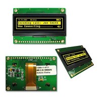
NHD-2.23-12832UCY3
Description
LCD OLED GRAPHIC 128 X 32 YLW
Manufacturer
Newhaven Display
Datasheet
1.NHD-2.23-12832UCY3.pdf
(14 pages)
Specifications of NHD-2.23-12832UCY3
Pixel Density
128 x 32
Viewing Area (w X H)
60 mm x 18 mm
Operating Voltage
2.85 V
Operating Current
28 mA
Maximum Operating Temperature
+ 85 C
Minimum Operating Temperature
- 40 C
Illumination Color
Yellow
Viewing Angle
80 deg
Lead Free Status / Rohs Status
Lead free / RoHS Compliant


Built‐in SSD1305 controller.
Instruction Table
Set Lower Column
Start Address
Set Higher
Column Start
Address
Set Memory
Addressing Mode
Set Column
Address
Set Page Address
Set Display Start
Line
Set Contrast
Control
Set Brightness
Set Look‐Up Table
Set Bank Color of
Bank1 to Bank16
(Page 0)
Set Bank Color of
Instruction
D/C
0
0
0
0
0
0
0
0
0
0
0
00~ 0F
10~1F
A[1:0]
A[7:0]
B[7:0]
A[2:0]
B[2:0]
40~7F
A[7:0]
A[7:0]
X[5:0]
A[5:0]
B[5:0]
C[5:0]
A[7:0]
B[7:0]
C[7:0]
D[7:0]
HEX
20
21
22
81
82
91
92
93
DB7
D7
A7
B7
A7
A7
A7
B7
C7
0
0
0
*
0
0
*
*
0
1
1
1
*
*
*
*
1
1
DB6
A6
B6
A6
A6
A6
B6
C6
D6
0
0
0
*
0
0
*
*
1
0
0
0
*
*
*
*
0
0
DB5
A5
B5
X5
A5
A5
X5
A5
B5
A5
B5
D5
C5
C5
0
0
1
*
1
1
*
*
0
0
0
0
0
Code
DB4
A4
A4
A4
A4
A4
D4
B4
X4
X4
B4
C4
B4
C4
0
1
0
*
0
0
*
*
0
0
1
1
1
DB3
A3
A3
A3
A3
A3
D3
X3
X3
B3
X3
X3
B3
C3
B3
C3
0
*
0
0
*
*
0
0
0
0
0
DB2
D2
X2
X2
A2
B2
A2
B2
X2
A2
A2
X2
A2
B2
C2
A2
B2
C2
0
0
0
0
0
0
*
0
0
DB1
X1
X1
A1
A1
B1
A1
B1
X1
A1
A1
X1
A1
B1
C1
A1
B1
C1
D1
[8]
0
0
1
0
1
0
1
1
DB0
X0
X0
A0
A0
B0
A0
B0
X0
A0
A0
X0
A0
B0
A0
B0
D0
C0
C0
0
1
0
1
0
1
0
1
Set the lower nibble of the column start address register for Page
Addressing Mode.
Set the higher nibble of the column start address register for Page
Addressing Mode.
A[1:0] = 00b, Horizontal Addressing Mode
A[1:0] = 01b, Vertical Addressing Mode
A[1:0] = 10b, Page Addressing Mode
A[1:0] = 11b, Invalid
Setup column start and end address
A[7:0]: Column start address. Range: 0‐131d
B[7:0]: Column end address. Range: 0‐131d
Setup page start and end address
A[2:0]: Page start address. Range: 0‐7d
B[2:0]: Page end address. Range: 0‐7d
Set display RAM display start line register from 0‐63d.
Double byte command to select 1 out of 256 contrast steps. Contrast
increases as the value increases.
Double byte command to select 1 out of 256 brightness steps.
Brightness increases as the value increases.
Set current drive pulse width of Bank 0, Color A, B and C.
Bank 0: X[5:0] = 31 to 63. Pulse width set to 32 to 64 clocks.
Color A: X[5:0] = 31 to 63. Pulse width set to 32 to 64 clocks.
Color B: X[5:0] = 31 to 63. Pulse width set to 32 to 64 clocks.
Color C: X[5:0] = 31 to 63. Pulse width set to 32 to 64 clocks.
Note: Color D pulse width is fixed at 64 clocks.
Sets the bank color of Bank1~Bank16 to any one of the 4 colors A,B,C,
and D.
A[1:0] : 00b, 01b, 10b, or 11b for Color = A, B, C, or D of BANK1.
A[3:2] : 00b, 01b, 10b, or 11b for Color = A, B, C, or D of BANK2.
.
.
.
D[5:4] : 00b, 01b, 10b, or 11b for Color = A, B, C, or D of BANK15.
D[7:6] : 00b, 01b, 10b, or 11b for Color = A, B, C, or D of BANK16.
Sets the bank color of Bank17~Bank32 to any one of the 4 colors
Description
RESET
value
131d
0x80
0x80
0x31
0x3F
0x3F
0x3F
10b
7d
0
0
0
0
0
Related parts for NHD-2.23-12832UCY3
Image
Part Number
Description
Manufacturer
Datasheet
Request
R

Part Number:
Description:
LCD OLED GRAPHIC 128 X 32 BLUE
Manufacturer:
Newhaven Display
Datasheet:

Part Number:
Description:
DISPLAY VFD ALPHA 1X20 6.5MM
Manufacturer:
Newhaven Display
Datasheet:

Part Number:
Description:
DISPLAY VFD ALPHA 1X16 5MM
Manufacturer:
Newhaven Display
Datasheet:

Part Number:
Description:
DISPLAY VFD 7-SEG 1X9 9.7MM
Manufacturer:
Newhaven Display
Datasheet:

Part Number:
Description:
DISPLAY VFD 7-SEG 1X6 20MM
Manufacturer:
Newhaven Display
Datasheet:

Part Number:
Description:
DISPLAY VFD 7-SEG 1X19 11MM
Manufacturer:
Newhaven Display
Datasheet:

Part Number:
Description:
DISPLAY VFD 7-SEG 1X3 8MM
Manufacturer:
Newhaven Display
Datasheet:

Part Number:
Description:
DISPLAY VFD CUSTOM DVD
Manufacturer:
Newhaven Display
Datasheet:

Part Number:
Description:
DISPLAY VFD CUST AUDIO
Manufacturer:
Newhaven Display
Datasheet:

Part Number:
Description:
DISPLAY VFD CUST AUDIO
Manufacturer:
Newhaven Display
Datasheet:

Part Number:
Description:
DISPLAY VFD 7-SEG 1X5 7.6MM
Manufacturer:
Newhaven Display
Datasheet:

Part Number:
Description:
DISPLAY VFD CUST APPLIANCE
Manufacturer:
Newhaven Display
Datasheet:

Part Number:
Description:
DISPLAY VFD CUSTOM DVD
Manufacturer:
Newhaven Display
Datasheet:

Part Number:
Description:
DISPLAY VFD 7-SEG 1X4 7.6MM
Manufacturer:
Newhaven Display
Datasheet:

Part Number:
Description:
DISPLAY VFD 7-SEG 1X9 8MM
Manufacturer:
Newhaven Display
Datasheet: