SY89829UHY Micrel Inc, SY89829UHY Datasheet - Page 6
SY89829UHY
Manufacturer Part Number
SY89829UHY
Description
2.5/3.3V Dual 1:10LVPECL Fanout/Translator (I Temp, )
Manufacturer
Micrel Inc
Type
Fanout Buffer (Distribution), Multiplexerr
Series
Precision Edge®r
Datasheet
1.SY89829UHY.pdf
(10 pages)
Specifications of SY89829UHY
Number Of Circuits
2
Ratio - Input:output
2:10
Differential - Input:output
Yes/Yes
Input
LVDS, LVPECL
Output
LVPECL
Frequency - Max
2GHz
Voltage - Supply
2.37 V ~ 3.6 V
Operating Temperature
-40°C ~ 85°C
Mounting Type
Surface Mount
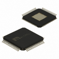
Package / Case
64-TQFP Exposed Pad, 64-eTQFP, 64-HTQFP, 64-VQFP
Frequency-max
2GHz
Number Of Clock Inputs
4
Mode Of Operation
Differential
Output Frequency
2000MHz
Output Logic Level
LVPECL
Operating Supply Voltage (min)
2.37V
Operating Supply Voltage (typ)
2.5/3.3V
Operating Supply Voltage (max)
3.6V
Package Type
TQFP EP
Operating Temp Range
-40C to 85C
Operating Temperature Classification
Industrial
Signal Type
LVDS/LVPECL
Mounting
Surface Mount
Pin Count
64
Lead Free Status / RoHS Status
Lead free / RoHS Compliant
Other names
576-2092
SY89829UHY
SY89829UHY
Available stocks
Company
Part Number
Manufacturer
Quantity
Price
Company:

Part Number:
SY89829UHY
Manufacturer:
MICREL
Quantity:
1 061


Micrel, Inc.
V
NOTES:
1. Outputs loaded with 50
2. f
3. Differential propagation delay is defined as the delay from the crossing point of the differential input signals to the crossing point of the differential
4. The within-device skew is defined as the worst case difference between any two similar delay paths within a single device operating at the same
5. The part-to-part skew is defined as the absolute worst case difference between any two delay paths on any two devices operating at the same
6. Set-up and hold time applies to synchronous applications that intend to enable/disable before the next clock cycle. For asynchronous applications,
M9999-011907
hbwhelp@micrel.com or (408) 955-1690
Symbol
f
t
t
t
t
t
t
t
CC
MAX
PD
SKEW
S(OE)
H(OE)
r
f
(switchover)
AC ELECTRICAL CHARACTERISTICS
output signals.
voltage and temperature.
voltage and temperature. Part-to-part skew is the total skew difference; pin-to-pin skew + part-to-part skew.
set-up and hold time does not apply. OE set-up time is defined with respect to the rising edge of the clock. OE HIGH to LOW transition ensures
outputs remain disabled during the next clock cycle. OE LOW to HIGH transition enables normal operation of the next input clock.
MAX
= 2.37V to 3.6V, GND = 0V
is defined as the maximum toggle frequency measured. Measured with a 750mV input signal, all loading with 50 to V
Max Toggle Frequency
Propagation Delay
(Differential)
Within-Device Skew
Part-to-Part Skew
OE Set-Up Time
OE Hold Time
Output Rise/Fall Time
(20% – 80%)
Input Switchover
CLK_SEL-to-valid output
Parameter
to V
(3)
(6)
CC
(6)
(5)
– 2V. Airflow
LVPECL IN
(4)
LVDS IN
(2)
300lfpm.
0.900
Min.
300
1.1
1.0
0.5
—
—
—
2
T
A
(1)
= –40 C
Typ.
100
—
—
—
—
—
—
—
—
Max.
6
200
600
1.5
1.7
1.2
35
—
—
—
0.900
Min.
300
1.1
1.0
0.5
—
—
—
2
T
A
= +25 C
Typ.
100
450
1.2
20
—
—
—
—
—
Max.
200
600
1.5
1.7
1.2
—
35
—
—
0.900
Min.
300
1.1
1.0
0.5
—
—
—
2
T
A
= +85 C
Typ.
100
CC
—
—
—
—
—
—
—
—
–2V.
Precision Edge
Max.
200
600
1.5
1.7
1.2
35
—
—
—
SY89829U
Unit
GHz
ns
ps
ps
ns
ns
ps
ns
®
Related parts for SY89829UHY
Image
Part Number
Description
Manufacturer
Datasheet
Request
R

Part Number:
Description:
3.3V 800MHz Ultrasmall Dual LVTTL-to-LVPECL Translator (I Temp, Green)
Manufacturer:
Micrel Inc
Datasheet:

Part Number:
Description:
IC XPOINT SW 4X4 PREC 44-MLF
Manufacturer:
Micrel Inc
Datasheet:
Part Number:
Description:
IC XPOINT SWITCH 3.2GBPS 44-MLF
Manufacturer:
Micrel Inc
Datasheet:
Part Number:
Description:
IC XPOINT SWITCH 3.2GBPS 44-MLF
Manufacturer:
Micrel Inc
Datasheet:
Part Number:
Description:
IC XPOINT SWITCH 4X4 LVDS 44-MLF
Manufacturer:
Micrel Inc
Datasheet:
Part Number:
Description:
IC XPOINT SWITCH 4X4 LVDS 44-MLF
Manufacturer:
Micrel Inc
Datasheet:

Part Number:
Description:
IC MUX 2:1 LVPECL DIFF 16MLF
Manufacturer:
Micrel Inc
Datasheet:
Part Number:
Description:
IC MUX 2:1 LVPECL RPE/FSI 16MLF
Manufacturer:
Micrel Inc
Datasheet:
Part Number:
Description:
IC MUX 2:1 LVDS RPE 16-MLF
Manufacturer:
Micrel Inc
Datasheet:
Part Number:
Description:
IC MUX 8:1 PREC LP 44-MLF
Manufacturer:
Micrel Inc
Datasheet:

Part Number:
Description:
IC MUX 2:1 LVDC DUAL 3.3V 32MLF
Manufacturer:
Micrel Inc
Datasheet:
Part Number:
Description:
IC MUX 4:1 LVDS DIFF 2.5V 32MLF
Manufacturer:
Micrel Inc
Datasheet:
Part Number:
Description:
IC MUX 4:1 LVDS DIFF 3.3V 32MLF
Manufacturer:
Micrel Inc
Datasheet:
Part Number:
Description:
IC MUX 4:1 LVDS DIFF 2.5V 32MLF
Manufacturer:
Micrel Inc
Datasheet:
Part Number:
Description:
IC MUX 4:1 LVDS DIFF 3.3V 32MLF
Manufacturer:
Micrel Inc
Datasheet: