2-830613-2 TE Connectivity, 2-830613-2 Datasheet
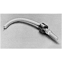
Cable Assembly Lead 0.3556m 16AWG LGH

2-830613-2

Manufacturer Part Number
2-830613-2
Description
Cable Assembly Lead 0.3556m 16AWG LGH
Manufacturer
TE Connectivity
Datasheets

Specifications of 2-830613-2

Connector Type
LGH
Cable Type
Lead
Cable Length
0.356 m
Product Type
Lead Assembly
Mount Angle
Straight
Cap Material
Glass-Filled Epoxy
Wire Size (mm² [awg])
16
Operating Voltage (kvdc)
15
Shielded
No
Lead Assembly Type
Single-End
Assembly Length (mm [in])
355.60 [14.000]
Barrel Depth (mm [in])
22.61 [0.890]
Positive Stop Ferrule
Without
Wire Color
White (Standard)
Cap Color
Green
Pigtail Length (mm [in])
9.65 [0.380]
Wire Diameter (mm [in])
4.22 [0.166]
Wire Insulation
Silicone
Preloaded
Yes
Rohs/elv Compliance
ELV compliant
Lead Free Solder Processes
Not relevant for lead free process
Rohs/elv Compliance History
Always was ELV compliant
DESIGN OBJECTIVES
The product described in this document has not been fully tested to ensure conformance to the requirements outlined below. Therefore
Tyco Electronics makes no representation or warranty, express or implied, that the product will comply with these requirements. Further,
Tyco Electronics may change these requirements based on the results of additional testing and evaluation. Contact Tyco Electronics
Engineering for further details.
1.
1.1.
1.2.
2.
2.1.
2.2.
2.3.
3.
3.1.
©2011 Tyco Electronics Corporation,
a TE Connectivity Ltd. Company
All Rights Reserved
TE logo is a trademark.
SCOPE
Content
This specification covers perform ance, tests and quality requirem ents for the Tyco Electronics LGH
standard high voltage 1/2I, 1/2LI, 1I, 1LI, 2I, 3I and 4I series m olded end leads and receptacles. These
leads and receptacles are designed for com m ercial, industrial and m ilitary type applications requiring
operation over wide environm ents.
Qualification
W hen tests are perform ed on the subject product line, procedures specified in Figure 1 shall be used.
All inspections shall be perform ed using the applicable inspection plan and product drawing.
APPLICABLE DOCUM ENTS
The following docum ents form a part of this specification to the extent specified herein. Unless
otherwise specified, the latest edition of the docum ent applies. In the event of conflict between the
requirem ents of this specification and the product drawing, the product drawing shall take precedence.
In the event of conflict between the requirem ents of this specification and the referenced docum ents,
this specification shall take precedence.
Tyco Electronics Docum ents
!
!
!
!
Com m ercial Standard
EIA-364:
Military Standard
MIL-STD-202: Test Methods For Electronic And Electrical Com ponent Parts
REQUIREM ENTS
Design and Construction
Product shall be of the design, construction and physical dim ensions specified on the applicable product
drawing.
109 Series: Test Specifications as indicated in Figure 1
109-197: Test Specification (AMP Test Specifications vs EIA and IEC Test Methods)
114-
501-
: Application Specification
: Qualification Test Report
PRELIMINARY
Electrical Connector/Socket Test Procedures Including Environm ental Classifications
| Indicates change
*Trademark
Design
Objectives
Standard LGH Connectors,
Series 1/2I, 1/2LI, 1I, 1LI, 2I, 3I and 4I
For latest revision, visit our website at www.te.com/documents.
For Regional Customer Service, visit our website at www.te.com
Other products, logos, and company names might be trademarks of their respective owners.
108-36033
Rev O2
1 of 6
LOC B

Related parts for 2-830613-2

2-830613-2 Summary of contents

Page 1

... This specification covers perform ance, tests and quality requirem ents for the Tyco Electronics LGH standard high voltage 1/2I, 1/2LI, 1I, 1LI, 2I, 3I and 4I series m olded end leads and receptacles. These leads and receptacles are designed for com m ercial, industrial and m ilitary type applications requiring operation over wide environm ents ...

Page 2

... Tem perature: -55 to 125 C 3.4. Perform ance and Test Description Product is designed to m eet the electrical, m echanical and environm ental perform ance requirem ents specified in Figure 1. Unless otherwise specified, all tests shall be perform bient environm ental conditions per EIA-364. ...

Page 3

... See Figure 4. AMP Spec 109-35. Size 3 tim es using gage 2. Then insert gage 1 to depth of .19 inch for 1/2I and 1/2LI and .25 inch for 1I, 1LI, 2I, 3I and 4I and m easure force necessary to separate. See Figure 4. EIA-364-32. Subject specim ens to 5 cycles between -55 and 125 C. ...

Page 4

... Rev O2 Requirem ent See Note. -8 Leakage rate less than He/sec. See Note. Figure 1 (end) Test or Exam ination Test Sequence (b) 3,11,15 Figure 2 108-36033 Procedure MIL-STD 202, Method 105C, Condition C. MIL-STD 202, Method 112C, Condition C. Test Group (a) 1 2(c) 1,19 1,18 4,8 5 4,13,17 ...

Page 5

... Test group 1 shall consist of 28 lead assem blies and receptacles; 4 each from 1/2I, 1/2LI, LI, 1LI, 2I, 3I and 4I series. Test group 2 shall consist of 14 herm etic seal type receptacles; 2 each from 1/2I, 1/2LI, LI, 1LI, 2I, 3I and 4I series. ...

Page 6

... Gage Num ber 1 2 (a) Contact: Size 16 NOTE (b) Material: Tungsten carbide Rev O2 Figure 3 Contact Resistance Measurem ent Points A Dim ension .0165 +.0001/-.0000 .0635 +.0000/-.0001 Figure 4 Engaging & Separating Gage 108-36033 B Dim ension Maxim um flat .015 ...

Related keywords