2N6667G ON Semiconductor, 2N6667G Datasheet
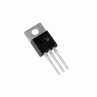
TRANS DARL PNP 10A 60V TO220AB

2N6667G

Manufacturer Part Number
2N6667G
Description
TRANS DARL PNP 10A 60V TO220AB
Manufacturer
ON Semiconductor
Datasheet

Specifications of 2N6667G

Transistor Type
PNP - Darlington
Current - Collector (ic) (max)
10A
Voltage - Collector Emitter Breakdown (max)
60V
Vce Saturation (max) @ Ib, Ic
3V @ 100mA, 10A
Current - Collector Cutoff (max)
1mA
Dc Current Gain (hfe) (min) @ Ic, Vce
1000 @ 5A, 3V
Power - Max
2W
Mounting Type
Through Hole
Package / Case
TO-220-3 (Straight Leads)
Polarity
PNP
Number Of Elements
1
Collector-emitter Voltage
60V
Collector-base Voltage(max)
60V
Emitter-base Voltage (max)
5V
Collector Current (dc) (max)
10A
Operating Temp Range
-65C to 150C
Operating Temperature Classification
Military
Mounting
Through Hole
Pin Count
3 +Tab
Package Type
TO-220
Configuration
Single
Transistor Polarity
PNP
Mounting Style
Through Hole
Collector- Emitter Voltage Vceo Max
60 V
Emitter- Base Voltage Vebo
5 V
Collector- Base Voltage Vcbo
60 V
Maximum Dc Collector Current
10 A
Maximum Collector Cut-off Current
1000 uA
Power Dissipation
65 W
Maximum Operating Temperature
+ 150 C
Continuous Collector Current
10 A
Dc Collector/base Gain Hfe Min
1000
Minimum Operating Temperature
- 65 C
Collector Emitter Voltage V(br)ceo
60V
Power Dissipation Pd
2W
Dc Collector Current
-10A
Dc Current Gain Hfe
20
Operating Temperature Range
-65°C To +150°C
Rohs Compliant
Yes
Lead Free Status / RoHS Status
Lead free / RoHS Compliant
Frequency - Transition
-
Lead Free Status / Rohs Status
Compliant
Other names
2N6667GOS
2N6667, 2N6668
Darlington Silicon
Power Transistors
applications.
*For additional information on our Pb-Free strategy and soldering details, please
© Semiconductor Components Industries, LLC, 2007
November, 2007 - Rev. 6
download the ON Semiconductor Soldering and Mounting Techniques
Reference Manual, SOLDERRM/D.
Designed for general-purpose amplifier and low speed switching
High DC Current Gain -
Collector-Emitter Sustaining Voltage - @ 200 mAdc
Low Collector-Emitter Saturation Voltage -
Monolithic Construction with Built-In Base-Emitter Shunt Resistors
TO-220AB Compact Package
Complementary to 2N6387, 2N6388
Pb-Free Packages are Available*
h
V
V
FE
CE(sat)
CEO(sus)
BASE
= 3500 (Typ) @ I
= 2.0 Vdc (Max)@ I
Figure 1. Darlington Schematic
= 60 Vdc (Min) - 2N6667
= 80 Vdc (Min) - 2N6668
≈ 8 k
C
= 4.0 Adc
≈ 120
COLLECTOR
EMITTER
C
= 5.0 Adc
1
2N6667
2N6667G
2N6668
2N6668G
1
Device
2
3
POWER TRANSISTORS
CASE 221A-09
ORDERING INFORMATION
10 A, 60-80 V, 65 W
TO-220AB
x
A
Y
WW = Work Week
G
STYLE 1:
DARLINGTON
http://onsemi.com
PNP SILICON
PIN 1. BASE
= 7 or 8
= Assembly Location
= Year
= Pb-Free Package
4
TO-220AB
TO-220AB
TO-220AB
TO-220AB
(Pb-Free)
(Pb-Free)
2. COLLECTOR
3. EMITTER
4. COLLECTOR
Package
Publication Order Number:
MARKING
DIAGRAM
50 Units/Rail
50 Units/Rail
50 Units/Rail
50 Units/Rail
AYWWG
2N666x
Shipping
2N6667/D

Related parts for 2N6667G

2N6667G Summary of contents

Page 1

... EMITTER 2 4. COLLECTOR 3 CASE 221A-09 TO-220AB Assembly Location Y = Year WW = Work Week G = Pb-Free Package ORDERING INFORMATION Device Package 2N6667 TO-220AB 2N6667G TO-220AB (Pb-Free) 2N6668 TO-220AB 2N6668G TO-220AB (Pb-Free) 1 MARKING DIAGRAM 2N666x AYWWG Shipping 50 Units/Rail 50 Units/Rail 50 Units/Rail 50 Units/Rail Publication Order Number: 2N6667/D ...

Page 2

MAXIMUM RATINGS (Note 1) Î Î Î ...

Page 3

R & R VARIED TO OBTAIN DESIRED CURRENT LEVELS MUST BE FAST RECOVERY TYPES e.g 100 mA 1N5825 USED ABOVE 100 mA MSD6100 USED BELOW I B FOR t AND t ...

Page 4

T = 150°C J 0.3 0.2 BONDING WIRE LIMIT 0.1 THERMAL LIMIT @ T = 25°C C SECOND BREAKDOWN LIMIT 0.05 CURVES APPLY BELOW RATED V 0.03 0. ...

Page 5

T = 25° 250 BE(sat 1 CE(sat) C 0.5 0.1 0.2 0.3 0.5 0 ...

Page 6

... PLANE American Technical Support: 800-282-9855 Toll Free USA/Canada Japan: ON Semiconductor, Japan Customer Focus Center  2-9-1 Kamimeguro, Meguro-ku, Tokyo, Japan 153-0051  Phone: 81-3-5773-3850 http://onsemi.com 6 NOTES: 1. DIMENSIONING AND TOLERANCING PER ANSI Y14.5M, 1982. 2. CONTROLLING DIMENSION: INCH. 3. DIMENSION Z DEFINES A ZONE WHERE ALL BODY AND LEAD IRREGULARITIES ARE ALLOWED ...

Related keywords