ZXM61P02FTA Diodes Zetex, ZXM61P02FTA Datasheet - Page 4
ZXM61P02FTA
Manufacturer Part Number
ZXM61P02FTA
Description
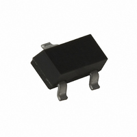
MOSFET P-CH 20V 900MA SOT23-3
Manufacturer
Diodes Zetex
Type
Small Signalr
Datasheet
1.ZXM61P02FTA.pdf
(7 pages)
Specifications of ZXM61P02FTA
Fet Type
MOSFET P-Channel, Metal Oxide
Fet Feature
Logic Level Gate
Rds On (max) @ Id, Vgs
600 mOhm @ 610mA, 4.5V
Drain To Source Voltage (vdss)
20V
Current - Continuous Drain (id) @ 25° C
900mA
Vgs(th) (max) @ Id
700mV @ 250µA
Gate Charge (qg) @ Vgs
3.5nc @ 4.5V
Input Capacitance (ciss) @ Vds
150pF @ 15V
Power - Max
625mW
Mounting Type
Surface Mount
Package / Case
SOT-23-3, TO-236-3, Micro3™, SSD3, SST3
Number Of Elements
1
Polarity
P
Channel Mode
Enhancement
Drain-source On-res
0.9Ohm
Drain-source On-volt
20V
Gate-source Voltage (max)
±12V
Continuous Drain Current
900mA
Power Dissipation
806mW
Operating Temp Range
-55C to 150C
Operating Temperature Classification
Military
Mounting
Surface Mount
Pin Count
3
Package Type
SOT-23
Lead Free Status / RoHS Status
Lead free / RoHS Compliant
Other names
ZXM61P02FTR
Available stocks
Company
Part Number
Manufacturer
Quantity
Price
Company:

Part Number:
ZXM61P02FTA
Manufacturer:
ZETEX
Quantity:
3 000
Part Number:
ZXM61P02FTA
Manufacturer:
ZETEX
Quantity:
20 000
Part Number:
ZXM61P02FTA/P02
Manufacturer:
TOREX/特瑞仕
Quantity:
20 000


ELECTRICAL CHARACTERISTICS (at T
(1) Measured under pulsed conditions. Width=300 s. Duty cycle 2% .
(2) Switching characteristics are independent of operating junction temperature.
(3) For design aid only, not subject to production testing.
ISSUE 1 - JUNE 2004
PARAMETER
STATIC
Drain-Source Breakdown Voltage
Zero Gate Voltage Drain Current
Gate-Body Leakage
Gate-Source Threshold Voltage
Static Drain-Source On-State Resistance
(1)
Forward Transconductance (3)
DYNAMIC (3)
Input Capacitance
Output Capacitance
Reverse Transfer Capacitance
SWITCHING(2) (3)
Turn-On Delay Time
Rise Time
Turn-Off Delay Time
Fall Time
Total Gate Charge
Gate-Source Charge
Gate Drain Charge
SOURCE-DRAIN DIODE
Diode Forward Voltage (1)
Reverse Recovery Time (3)
Reverse Recovery Charge(3)
ZXM61P02F
SYMBOL MIN.
V
I
I
V
R
g
C
C
C
t
t
t
t
Q
Q
Q
V
t
Q
DSS
GSS
d(on)
r
d(off)
f
rr
fs
(BR)DSS
GS(th)
DS(on)
iss
oss
rss
SD
g
gs
gd
rr
4
-20
-0.7
0.56
amb
= 25°C unless otherwise stated).
TYP.
150
70
30
2.9
6.7
11.2
10.1
14.9
5.6
MAX.
-1
0.6
0.9
3.5
0.5
1.5
-0.95
100
UNIT CONDITIONS.
V
nA
V
S
pF
pF
pF
ns
ns
ns
ns
nC
nC
nC
V
ns
nC
A
I
V
V
I
V
V
V
V
f=1MHz
V
R
(Refer to test circuit)
V
I
(Refer to test circuit)
T
V
T
di/dt= 100A/ s
D
D
D
j
j
DS
GS
GS
GS
DS
DS
DD
G
DS
GS
=-250 A, V
=-250 A, V
=-0.61A
=25°C, I
=25°C, I
=6.2 , R
=-20V, V
=-10V,I
=-15 V, V
=-16V,V
= 12V, V
=-4.5V, I
=-2.7V, I
=0V
=-10V, I
S
F
D
=-0.61A,
=-0.61A,
D
GS
=-0.31A
D
D
D
GS
=11
GS
=-0.93A
GS
DS
=-0.61A
=-0.31A
DS
=-4.5V,
=0V
=0V,
=0V
= V
=0V
GS
Related parts for ZXM61P02FTA
Image
Part Number
Description
Manufacturer
Datasheet
Request
R

Part Number:
Description:
DIODE ZENER 13V 500MW SOD-123
Manufacturer:
Diodes Zetex
Datasheet:

Part Number:
Description:
DIODE ZENER 13V 200MW SOD-323
Manufacturer:
Diodes Zetex
Datasheet:

Part Number:
Description:
DIODE ZENER 27V 500MW MINIMELF
Manufacturer:
Diodes Zetex
Datasheet:
Part Number:
Description:
DIODE ZENER 16V 200MW SOD-323
Manufacturer:
Diodes Zetex
Datasheet:
Part Number:
Description:
DIODE ZENER 28V 500MW SOD-123
Manufacturer:
Diodes Zetex
Datasheet:

Part Number:
Description:
DIODE ZENER 6.2V 200MW SC70-3
Manufacturer:
Diodes Zetex
Datasheet:

Part Number:
Description:
DIODE ZENER 3.6V 350MW SOT23-3
Manufacturer:
Diodes Zetex
Datasheet:

Part Number:
Description:
DIODE ZENER 4.3V 350MW SOT23-3
Manufacturer:
Diodes Zetex
Datasheet:
Part Number:
Description:
DIODE ZENER 13V 350MW SOT23-3
Manufacturer:
Diodes Zetex
Datasheet:
Part Number:
Description:
DIODE ZENER 16V 350MW SOT23-3
Manufacturer:
Diodes Zetex
Datasheet:

Part Number:
Description:
DIODE SW ARRAY 80V 200MW SOT363
Manufacturer:
Diodes Zetex
Datasheet:

Part Number:
Description:
DIODE SCHOTTKY 45V16A TO220-3
Manufacturer:
Diodes Zetex
Datasheet:
Part Number:
Description:
DIODE SCHOTTKY 45V 20A TO220-3
Manufacturer:
Diodes Zetex
Datasheet:
Part Number:
Description:
DIODE SW FAST DUAL CC SOT23-3
Manufacturer:
Diodes Zetex
Datasheet:
Part Number:
Description:
DIODE HI SPEED SW CC 70V SOT23-3
Manufacturer:
Diodes Zetex
Datasheet: