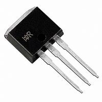
IRGSL10B60KDPBF International Rectifier, IRGSL10B60KDPBF Datasheet

IRGSL10B60KDPBF
Specifications of IRGSL10B60KDPBF
Related parts for IRGSL10B60KDPBF
IRGSL10B60KDPBF Summary of contents
Page 1
... Thermal Resistance Parameter R Junction-to-Case - IGBT θJC R Junction-to-Case - Diode θJC R Case-to-Sink, flat, greased surface θCS R Junction-to-Ambient, typical socket mount θJA R Junction-to-Ambient (PCB Mount, steady state) θJA Wt Weight www.irf.com IRGB10B60KDPbF IRGS10B60KDPbF IRGSL10B60KDPbF 600V CES I = 12A > 10µ n-channel CE(on) 2 TO-220AB D Pak IRGB10B60KD IRGS10B60KD Max ...
Page 2
IRG/B/S/SL10B60KDPbF Electrical Characteristics @ T Parameter V Collector-to-Emitter Breakdown Voltage (BR)CES ∆V Temperature Coeff. of Breakdown Voltage /∆T (BR)CES J V Collector-to-Emitter Saturation Voltage CE(on) V Gate Threshold Voltage GE(th) ∆ ∆ Temperature Coeff. of Threshold Voltage ...
Page 3
T C (°C) Fig Maximum DC Collector Current vs. Case Temperature 100 0 100 V CE (V) Fig. ...
Page 4
IRG/B/S/SL10B60KDPbF 18V 35 VGE = 15V VGE = 12V 30 VGE = 10V VGE = 8. (V) Fig Typ. IGBT Output Characteristics ...
Page 5
V GE (V) Fig Typical -40° 5. 10A 10 ...
Page 6
IRG/B/S/SL10B60KDPbF 800 700 600 500 E OFF 400 300 E ON 200 100 (A) Fig Typ. Energy Loss vs 150°C; L=200µ 47Ω 15V ...
Page 7
Ω Ω Ω 100 Ω (A) Fig Typical Diode I T ...
Page 8
IRG/B/S/SL10B60KDPbF 450 400 350 300 250 200 150 100 50 0 1000 100 (V) Fig. 22- Typ. Capacitance vs 0V 1MHz (A) ...
Page 9
D = 0.50 0.20 0.1 0.10 0.05 0.01 0.02 0.01 SINGLE PULSE ( THERMAL RESPONSE ) 0.001 1E-6 1E-5 Fig 24. Maximum Transient Thermal Impedance, Junction-to-Case (IGBT 0.50 1 0.20 0.10 0.05 0.01 0.1 0.02 0.01 ...
Page 10
IRG/B/S/SL10B60KDPbF DUT 0 1K Fig.C.T.1 - Gate Charge Circuit (turn-off) Driver DC DUT Fig.C.T.3 - S.C.SOA Circuit 10 L VCC diode clamp / 360V DUT Rg Fig.C.T.5 - Resistive Load ...
Page 11
I CE 300 tf 200 100 Eoff Loss -100 -0.20 0.00 0.20 0.40 time(µs) Fig. WF1- Typ. Turn-off Loss Waveform @ T = 150°C using Fig. CT.4 J 100 ...
Page 12
IRG/B/S/SL10B60KDPbF E XAMPL HIS 1010 L OT CODE 1789 19, 1997 INE "C" ...
Page 13
Dimensions are shown in millimeters (inches HIS IS AN IRF530S WIT H LOT CODE 8024 AS S EMBLED ON WW 02, 2000 EMBLY LINE "L" Note: "P" embly line ...
Page 14
IRG/B/S/SL10B60KDPbF TO-262 Package Outline Dimensions are shown in millimeters (inches) TO-262 Part Marking Information EXAMPLE HIS IS AN IRL3103L LOT CODE 1789 INT ERNAT IONAL ASS EMBLED ON WW 19, 1997 RECT IFIER ASS EMBLY ...
Page 15
Dimensions are shown in millimeters (inches) TRR FEED DIRECTION 1.85 (.073) 1.65 (.065) TRL 10.90 (.429) 10.70 (.421) FEED DIRECTION 13.50 (.532) 12.80 (.504) 330.00 (14.173) MAX. NOTES : 1. COMFORMS TO EIA-418. 2. CONTROLLING DIMENSION: MILLIMETER. 3. DIMENSION ...
Page 16
Note: For the most current drawings please refer to the IR website at: http://www.irf.com/package/ ...


