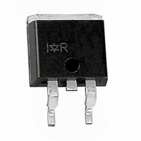
IRGS14C40LPBF International Rectifier, IRGS14C40LPBF Datasheet

IRGS14C40LPBF
Specifications of IRGS14C40LPBF
Available stocks
Related parts for IRGS14C40LPBF
IRGS14C40LPBF Summary of contents
Page 1
Absolute Maximum Ratings Parameter V Collector-to-Emitter Voltage CES 25°C Continuous Collector Current 110°C Continuous Collector Current Continuous Gate Current G I ...
Page 2
Off-State Electrical Charasteristics @ T Parameter Collector-to-Emitter Breakdown Voltage BV CES Gate-to-Emitter Breakdown Voltage BV GES Collector-to-Emitter Leakage Current I CES BV Emitter-to-Collector Breakdown Voltage CER R Gate Series Resistance 1 Gate-to-Emitter Resistance R 2 On-State Electrical Charasteristics @ T ...
Page 3
Fig.1 - Typ. Output Characteristics T =25° ...
Page 4
Fig.5 - Typical GE(th =1mA C 2.2 2.0 1.8 1.6 1.4 1.2 1.0 - 100 150 T (°C) J Fig.7 - Typ. Gate Charge =10A; V =12V; V =5V C ...
Page 5
Fig.9 - Self-clamp Avalance Current vs Inductance @ 25° Typical Minimum Inductance (mH 0.50 0.20 0.10 0.1 0.05 0.02 0.01 SINGLE PULSE (THERMAL RESPONSE) 0.01 ...
Page 6
Fig.12 - Switching Waveform for Time Measurement 450 400 350 300 250 200 150 100 -50 -14 -10 -6 Fig.13 - Self-clamped Inductive Switching Waveform L=4.7mH; T ...
Page 7
Ignition IGBT 0.47 Ω L D.U.T. Ice ...
Page 8
Dimensions are shown in millimeters (inches 530S WIT CODE 8024 02, 2000 ...
Page 9
TO-262 Package Outline Dimensions are shown in millimeters (inches) TO-262 Part Marking Information E XAMPL 3103L L OT CODE 1789 19, 1997 ...
Page 10
E XAMPL HIS 1010 L OT CODE 1789 19, 1997 INE "C" Note: ...
Page 11
Dimensions are shown in millimeters (inches) TRR FEED DIRECTION 1.85 (.073) 1.65 (.065) TRL 10.90 (.429) 10.70 (.421) FEED DIRECTION 13.50 (.532) 12.80 (.504) 330.00 (14.173) MAX. NOTES : 1. COMFORMS TO EIA-418. 2. CONTROLLING DIMENSION: MILLIMETER. 3. DIMENSION ...
Page 12
Note: For the most current drawings please refer to the IR website at: http://www.irf.com/package/ ...


