20CJQ100 Vishay, 20CJQ100 Datasheet - Page 2
20CJQ100
Manufacturer Part Number
20CJQ100
Description
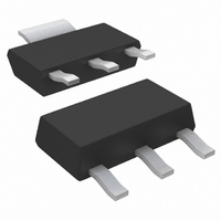
DIODE SCHOTTKY 100V 1A SOT-223
Manufacturer
Vishay
Specifications of 20CJQ100
Diode Configuration
1 Pair Common Cathode
Diode Type
Schottky
Voltage - Forward (vf) (max) @ If
790mV @ 1A
Current - Reverse Leakage @ Vr
100µA @ 1000V
Current - Average Rectified (io) (per Diode)
1A
Voltage - Dc Reverse (vr) (max)
100V
Speed
Fast Recovery =< 500ns, > 200mA (Io)
Mounting Type
Surface Mount
Package / Case
SOT-223 (3 leads + Tab), SC-73, TO-261
Product
Schottky Rectifiers
Peak Reverse Voltage
100 V
Forward Continuous Current
4 A
Max Surge Current
380 A
Configuration
Dual Common Cathode
Forward Voltage Drop
0.89 V at 2 A
Maximum Reverse Leakage Current
100 uA
Operating Temperature Range
- 55 C to + 175 C
Mounting Style
SMD/SMT
Repetitive Reverse Voltage Vrrm Max
100V
Forward Current If(av)
2A
Forward Voltage Vf Max
890mV
Lead Free Status / RoHS Status
Contains lead / RoHS non-compliant
Reverse Recovery Time (trr)
-
Lead Free Status / RoHS Status
Contains lead / RoHS non-compliant, Contains lead / RoHS non-compliant
Other names
*20CJQ100
VS-20CJQ100
VS-20CJQ100
VS20CJQ100
VS20CJQ100
VS-20CJQ100
VS-20CJQ100
VS20CJQ100
VS20CJQ100
Available stocks
Company
Part Number
Manufacturer
Quantity
Price
Company:

Part Number:
20CJQ100PBF
Manufacturer:
VISHAY
Quantity:
5 600
Company:
Part Number:
20CJQ100TRPBF
Manufacturer:
FREESCALE
Quantity:
2 100


Bulletin PD-20480 rev. H
20CJQ100
Thermal-Mechanical Specifications
2
Voltage Ratings
Absolute Maximum Ratings
Electrical Specifications
I
I
E
I
V
I
C
L
dv/dt Max. Voltage Rate of Change
T
T
R
R
wt
(1) Pulse Width < 300μs, Duty Cycle <2%
(*) dPtot
V
V
F(AV)
FSM
AR
RM
S
AS
J
stg
FM
T
thJA
thJL
R
RWM
dTj
Case Style
Device Marking
Max. Average Forward
Current
Max. Peak One Cycle Non-Repetitive
Surge Current (Per Leg) * See Fig. 7
Non-Repetitive Avalanche Energy
Repetitive Avalanche Current
Part number
Max. DC Reverse Voltage (V)
Max. Working Peak Reverse Voltage (V)
Parameters
Max. Forward Voltage Drop
(Per Leg) * See Fig. 1
Max. Reverse Leakage Current
(Per Leg) * See Fig. 2
Typ. Junction Capacitance (Per Leg)
Typical Series Inductance (Per Leg)
Parameters
Max. Junction Temperature Range (*) -55 to 175
Max. Storage Temperature Range
Max. Thermal Resistance
Junction to Ambient
Max. Thermal Resistance
Junction to Lead
Approximate Weight
Parameters
<
Rth( j-a)
1
* See Fig. 5 (Per Device)
thermal runaway condition for a diode on its own heatsink
07/06
(Per Leg)
(Per Leg)
(Per Leg)
(1)
(1)
0.13 (.0045) g (oz.)
-55 to 175
Values
Values Units
Values Units
10000
0.79
0.89
0.67
0.76
380
0.1
22
10
45
65
25
2
4
1
1
6
SOT-223
2CJQJ
Units
°C/W DC operation
°C/W
V/ μs (Rated V
mJ
mA
mA
nH
pF
°C
°C
A
A
A
V
V
V
V
50% duty cycle @ T
5μs Sine or 3μs Rect. pulse
10ms Sine or 6ms Rect. pulse
T
Current decaying linearly to zero in 1 μsec
Frequency limited by T
@ 1A
@ 2A
@ 1A
@ 2A
T
T
V
Measured lead to lead 5mm from package body
J
J
J
R
= 25 °C, I
= 25 °C
= 125 °C
= 5V
DC
R
)
(test signal range 100Khz to 1Mhz) 25°C
Conditions
Conditions
Conditions
AS
= 1 Amps, L = 2 mH
20CJQ100
T
V
T
J
J
R
= 25 °C
= 125 °C
= rated V
C
100
= 129°C, rectangular wave form
J
max. V
R
Following any rated
load condition and with
rated V
A
= 1.5 x V
RRM
www.irf.com
R
applied
typical
Related parts for 20CJQ100
Image
Part Number
Description
Manufacturer
Datasheet
Request
R

Part Number:
Description:
357-036-542-201 CARDEDGE 36POS DL .156 BLK LOPRO
Manufacturer:
Vishay
Datasheet:
Part Number:
Description:
357-036-542-201 CARDEDGE 36POS DL .156 BLK LOPRO
Manufacturer:
Vishay
Datasheet:
Part Number:
Description:
357-036-542-201 CARDEDGE 36POS DL .156 BLK LOPRO
Manufacturer:
Vishay
Datasheet:
Part Number:
Description:
357-036-542-201 CARDEDGE 36POS DL .156 BLK LOPRO
Manufacturer:
Vishay
Datasheet:
Part Number:
Description:
357-036-542-201 CARDEDGE 36POS DL .156 BLK LOPRO
Manufacturer:
Vishay
Datasheet:
Part Number:
Description:
357-036-542-201 CARDEDGE 36POS DL .156 BLK LOPRO
Manufacturer:
Vishay
Datasheet:
Part Number:
Description:
357-036-542-201 CARDEDGE 36POS DL .156 BLK LOPRO
Manufacturer:
Vishay
Datasheet:
Part Number:
Description:
357-036-542-201 CARDEDGE 36POS DL .156 BLK LOPRO
Manufacturer:
Vishay
Datasheet:
Part Number:
Description:
357-036-542-201 CARDEDGE 36POS DL .156 BLK LOPRO
Manufacturer:
Vishay
Datasheet:
Part Number:
Description:
357-036-542-201 CARDEDGE 36POS DL .156 BLK LOPRO
Manufacturer:
Vishay
Datasheet:
Part Number:
Description:
357-036-542-201 CARDEDGE 36POS DL .156 BLK LOPRO
Manufacturer:
Vishay
Datasheet:
Part Number:
Description:
357-036-542-201 CARDEDGE 36POS DL .156 BLK LOPRO
Manufacturer:
Vishay
Datasheet:
Part Number:
Description:
357-036-542-201 CARDEDGE 36POS DL .156 BLK LOPRO
Manufacturer:
Vishay
Datasheet:
Part Number:
Description:
357-036-542-201 CARDEDGE 36POS DL .156 BLK LOPRO
Manufacturer:
Vishay
Datasheet:
Part Number:
Description:
357-036-542-201 CARDEDGE 36POS DL .156 BLK LOPRO
Manufacturer:
Vishay
Datasheet: