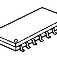
NJM2145M NJR, NJM2145M Datasheet

NJM2145M
Specifications of NJM2145M
Available stocks
Related parts for NJM2145M
NJM2145M Summary of contents
Page 1
... Internal Error Protection Circuit against open OUT2 terminal • OUT2 (Tow-Way • Internal Output Short Protection • Bipolar Technology • Package Outline DIP16, DMP16 ■ PIN CONFIGURATION ■ BLOCK DIAGRAM Ver.2003-12-09 ■ PACKAGE OUTLINE NJM2145D NJM2145M PIN FUNCTION + OUT2-3 2. OUT1 10. OUT2-2 3. IN4 11. OUT2-1 4. IN3 12 ...
Page 2
ABSOLUTE MAXIMUM RATINGS PARAMETER Supply Voltage Power Dissipation Operating Temperature Range Storage Temperature Range ■ ELECTRICAL CHARACTERISTICS (V PARAMETER SYMBOL Operating Supply Voltage V opr Operating Current 1 Icc1 Operating Current 2 Icc2 IN1-High Electric Potential IN1-H1 Output Voltage1 ...
Page 3
ELECTRICAL CHARACTERISTICS (V PARAMETER SYMBOL OUT1-High Electric Potential OUT1-H1 Output Voltage1 OUT1-High Electric Potential OUT1-H2 Output Voltage2 OUT1-Low Electric Potential OUT1-L Output Voltage OUT2-High Electric Potential OUT2-H1 Output Voltage1 OUT2-Low Electric Potential OUT2-L1 Output Voltage1 OUT2-High Electric Potential OUT2-H2 ...
Page 4
TEST CIRCUIT - 4 - Ver.2003-12-09 ...
Page 5
TYPICAL CHARACTERISTICS INHIBIT Time vs, Outside Capacitor Out 2 Output Voltage vs. Load Resistance Regulator Load Characteristics Ver.2003-12-09 INHIBIT Time vs. Temperture (Vcc1 = 5V 1000pF) Regulator Output Characteristics Ripple Rejection - 5 - ...
Page 6
The specifications on this databook are only given for information , without any guarantee as regards either mistakes or omissions. The application circuits in this databook are described only to show representative usages of the product ...


