ADXL001-70BEZ Analog Devices Inc, ADXL001-70BEZ Datasheet
ADXL001-70BEZ
Specifications of ADXL001-70BEZ
Available stocks


Related parts for ADXL001-70BEZ


ADXL001-70BEZ Summary of contents
Page 1
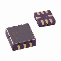
... The part can operate on voltage supplies from 3 The ADXL001 also has a self-test (ST) pin that can be asserted to verify the full electromechanical signal chain for the accelerometer channel. The ADXL001 is available in the industry-standard 8-terminal LCC and is rated to work over the extended industrial temperature range (− ...
Page 2
... ADXL001 TABLE OF CONTENTS Features .............................................................................................. 1 Applications ....................................................................................... 1 General Description ......................................................................... 1 Functional Block Diagram .............................................................. 1 Revision History ............................................................................... 2 Specifications ..................................................................................... 3 Specifications for 3.3 V Operation ............................................. 3 Specifications for 5 V Operation ................................................ 4 Recommended Soldering Profile ............................................... 5 Absolute Maximum Ratings ............................................................ 6 ESD Caution .................................................................................. 6 Pin Configuration and Function Descriptions ............................. 7 Typical Performance Characteristics ............................................. 8 Theory of Operation ...................................................................... 11 REVISION HISTORY 2/10— ...
Page 3
... V − 0.2 0.2 S 1000 1000 0.9 0.9 3.135 6 3.135 2 Rev Page ADXL001 ADXL001-500 Max Min Typ Max Unit 2 0 kHz 2.5 +250 −500 +500 g 2.2 mV/g 1.95 1.35 1.65 1.95 V 105 mg rms 4.25 mg/√Hz ...
Page 4
... V − 0.2 0.2 S 1000 1000 0.9 0.9 3.135 6 3.135 4 Rev Page ADXL001-500 Max Min Typ Max Unit 2 0 kHz 2.5 +250 −500 +500 g 3.3 mV/g 3.00 2.00 2.5 3. rms 2.76 mg/√Hz 32 kHz 2 % 217 mV 3 ...
Page 5
... RAMP-DOWN PREHEAT t PEAK TIME (t) Figure 3. Soldering Profile Diagram Rev Page Pb-Free 3°C/sec maximum 150°C 200°C 60 sec to 150 sec 3°C/sec 217°C 60 sec to 150 sec 260°C + 0°C/−5°C 20 sec to 40 sec 6°C/sec maximum 8 minute maximum CRITICAL ZONE ADXL001 ...
Page 6
... ADXL001 ABSOLUTE MAXIMUM RATINGS Table 4. Parameter Acceleration (Any Axis, Unpowered and Powered) Supply Voltage Output Short-Circuit Duration (V to GND) OUT Storage Temperature Range Operating Temperature Range Soldering Temperature (Soldering, 10 sec) Stresses above those listed under Absolute Maximum Ratings may cause permanent damage to the device. This is a stress rating only ...
Page 7
... Do Not Connect. 3 COM Common Self-Test Control (Logic Input X-Axis Acceleration Output. OUT 7 V 3.135 Connect 3.135 Connect to V DD2 V DD2 8 DNC DNC OUT COM 3 5 DNC 4 ST DNC = DO NOT CONNECT ADXL001 TOP VIEW (Not to Scale) Figure 4. Pin Configuration . DD2 . DD Rev Page ADXL001 ...
Page 8
... Figure 5. Zero-g Bias Deviation from Ideal VOLTS Figure 6. Zero-g Bias Deviation from Ideal ( (mV/g) Figure 7. ADXL001-70, Sensitivity Distribution Figure 8. ADXL001-70, Sensitivity Distribution ( 125° Figure 10: ADXL001-250, Sensitivity Distribution (T Rev Page (mV/g) = 125°C) A (mV/g) Figure 9: ADXL001-250, Sensitivity Distribution (mV/g) = 125°C) A ...
Page 9
... Figure 11. ADXL001-500, Sensitivity Distribution (mV/g) Figure 12. ADXL001-500, Sensitivity Distribution ( (mV) Figure 13. ADXL001-70, Self-Test Delta 125° Rev Page ADXL001 (mV) Figure 14. ADXL001-250, Self-Test Delta (mV) Figure 15. ADXL001-500, Self-Test Delta (mA) Figure 16. I Distribution SUPPLY 67 ...
Page 10
... ADXL001 (mA) Figure 17 125°C SUPPLY B CH1 500mV CH2 500mV W Figure 18. Turn-On Characteristic (10 μs per DIV) Rev Page M10.0µs A CH2 1.38V W T 42.80% ...
Page 11
... Displacement of the sensor frame changes the differential capacitance. On-chip circuitry measures the capacitive change. MECHANICAL SENSOR The ADXL001 is built using the Analog Devices SOI MEMS sensor process. The sensor device is micromachined in-plane in the SOI device layer. Trench isolation is used to electrically isolate, but mechanically couple, the differential sensing elements ...
Page 12
... The fixed fingers in the forcing cells are normally kept at the same potential as that of the movable frame. When the digital self-test input is activated, the ADXL001 changes the voltage on the fixed fingers in these forcing cells on one side of the moving plate. This potential creates an attractive electrostatic force, causing the sensor to move toward those fixed fingers. The entire signal channel is active ...
Page 13
... The ADXL001 addresses this issue in two ways. First, the high clock frequency, 125 kHz for the output stage, eases the task of choosing a power supply clock frequency such that the difference between it and the accelerometer clock remains well outside the filter bandwidth ...
Page 14
... SQ 0.171 R 0.008 (4 PLCS) ORDERING GUIDE 1 Model Temperature Range ADXL001-70BEZ −40°C to +125°C ADXL001-70BEZ-R7 −40°C to +125°C ADXL001-250BEZ −40°C to +125°C ADXL001-250BEZ-R7 −40°C to +125°C ADXL001-500BEZ −40°C to +125°C ADXL001-500BEZ-R7 −40°C to +125°C EVAL-ADXL001-250Z ...
Page 15
... NOTES Rev Page ADXL001 ...
Page 16
... ADXL001 NOTES ©2010 Analog Devices, Inc. All rights reserved. Trademarks and registered trademarks are the property of their respective owners. D07510-0-2/10(A) Rev Page ...