HFCT-5953TL Avago Technologies US Inc., HFCT-5953TL Datasheet - Page 15
HFCT-5953TL
Manufacturer Part Number
HFCT-5953TL
Description
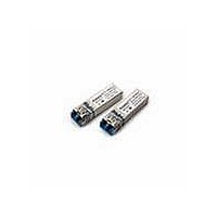
Fiber Optic Transmitters, Receivers, Transceivers OC12 IR 2x5 SFF LC
Manufacturer
Avago Technologies US Inc.
Datasheet
1.HFCT-5953TL.pdf
(17 pages)
Specifications of HFCT-5953TL
Function
High performance, modules for serial optical data communication applications, designed for single mode fiber.
Product
Transceiver
Data Rate
622 Mbps
Wavelength
1300 nm
Maximum Rise Time
1 ns, 0.5 ns
Maximum Fall Time
1 ns, 0.5 ns
Maximum Output Current
50 mA
Operating Supply Voltage
3.14 V to 3.47 V
Maximum Operating Temperature
+ 70 C
Minimum Operating Temperature
0 C
Package / Case
DIP-10 with Connector
Optical Fiber Type
TX/RX
Data Transfer Rate
622Mbps
Optical Rise Time
1/0.5ns
Optical Fall Time
1/0.5ns
Operating Temperature Classification
Commercial
Peak Wavelength
1356/1570nm
Package Type
DIP With Connector
Operating Supply Voltage (min)
3.14V
Operating Supply Voltage (typ)
3.3V
Operating Supply Voltage (max)
3.47V
Output Current
50mA
Operating Temp Range
0C to 70C
Mounting
Snap Fit To Panel
Pin Count
10
For Use With
Singlemode Glass
Lead Free Status / RoHS Status
Lead free / RoHS Compliant


Transmitter Electrical Characteristics for multirate operations at OC3 (155 Mbit/s) and OC12 (622 Mbit/s)
HFCT-5953TL/TG/HFCT-5954TL/TG: T
HFCT-5953ATL/ATG/HFCT-5954ATL/ATG: T
Receiver Electrical Characteristics for multirate operations at OC3 (155 Mbit/s) and OC12 (622 Mbit/s)
HFCT-5953TL/TG/HFCT-5954TL/TG: T
HFCT-5953ATL/ATG/HFCT-5954ATL/ATG: T
Notes:
1. Excludes data output termination currents.
2. The laser bias monitor current and laser diode optical power are calculated as ratios of the corresponding voltages to their current sensing
3. On the 2 x 10 version only.
4. Power dissipation value is the power dissipated in the receiver itself. It is calculated as the sum of the products of V
5. These outputs are compatible with 10 k, 10 kH, and 100 k ECL and PECL inputs.
6. These are 20-80% values.
7. SD is LVTTL compatible.
15
Parameter
Supply Current
Power Dissipation
Data Input Voltage Swing (single-ended)
Transmitter Differential Data Input Current - Low I
Transmitter Differential Data Input Current - High I
Laser Diode Bias Monitor Voltage
Power Monitor Voltage
Parameter
Supply Current
Power Dissipation
Data Output Voltage Swing (single-ended)
Data Output Rise Time
Data Output Fall Time
Signal Detect Output Voltage - Low
Signal Detect Output Voltage - High
Signal Detect Assert Time (OFF to ON)
Signal Detect Deassert Time (ON to OFF)
resistors, 10 W and 200 W (see Figure 7). On the 2 x 10 version only.
of the products of the output voltages and currents.
A
A
= 0°C to +70°C, V
= 0°C to +70°C, V
A
A
= -40°C to +85°C, V
= -40°C to +85°C, V
Symbol
I
P
V
Symbol
I
P
V
t
t
V
V
AS
ANS
CCT
IL
IH
CCR
r
f
DIST
DISR
IH
OH
OL
OH
MAX
- V
- V
MAX
IL
OL
CC
CC
= 3.14 V to 3.47 V
= 3.14 V to 3.47 V
Min.
250
-350
10
Min.
575
2.0
2.3
CC
CC
= 3.14 V to 3.47 V
= 3.14 V to 3.47 V
Typ.
30
0.10
800
Typ.
70
0.23
800
Max.
120
0.42
930
350
700
200
Max.
110
0.38
930
0.5
0.5
0.8
100
100
Unit
mA
W
mV
µA
µA
mV
mV
Unit
mA
W
mV
ns
ns
V
V
µs
µs
CC
and I
CC
minus the sum
Reference
1
2, 3
2, 3
Reference
1
4
5
6
6
7
7
Related parts for HFCT-5953TL
Image
Part Number
Description
Manufacturer
Datasheet
Request
R

Part Number:
Description:
TXRX SMF XFP 10BGE 2KM OC-192
Manufacturer:
Avago Technologies US Inc.
Datasheet:

Part Number:
Description:
Fiber Optic Transmitters, Receivers, Transceivers OC3 SFP IR -10 to +8 5 non-DMI
Manufacturer:
Avago Technologies US Inc.
Datasheet:

Part Number:
Description:
Fiber Optics, Transceiver Module
Manufacturer:
Avago Technologies US Inc.
Part Number:
Description:
Fiber Optic Transmitters, Receivers, Transceivers SFP OC12 IR Standard Delatch
Manufacturer:
Avago Technologies US Inc.

Part Number:
Description:
Manufacturer:
Avago Technologies
Datasheet:

Part Number:
Description:
155 Mb/s Single Mode Laser Transceiver For Atm, Sonet OC-3/SDH STM-1 (L1.1)
Manufacturer:
Agilent Technologies, Inc.
Datasheet:
Part Number:
Description:
Fiber Optics, Evaluation Kit
Manufacturer:
Avago Technologies US Inc.
Datasheet:
Part Number:
Description:
Fiber Optics, Evaluation Kit
Manufacturer:
Avago Technologies US Inc.
Datasheet:
Part Number:
Description:
Fiber Optics, Evaluation Kit
Manufacturer:
Avago Technologies US Inc.
Datasheet:

Part Number:
Description:
Agilent HFCT-5215B/D 155 Mb/s Single Mode Laser Transceiver
Manufacturer:
Hewlett-Packard
Datasheet:

Part Number:
Description:
OPTOCOUPLER GATE DRV 2A 16-SOIC
Manufacturer:
Avago Technologies US Inc.
Datasheet:
Part Number:
Description:
OPTOCOUPLER 2CH 2.5A 16-SOIC
Manufacturer:
Avago Technologies US Inc.
Datasheet:

Part Number:
Description:
OPTOCOUPLER GATE DRV 0.4A 16SOIC
Manufacturer:
Avago Technologies US Inc.
Datasheet:

Part Number:
Description:
OPTOCOUPLER 2.0A 250KHZ 8-DIP
Manufacturer:
Avago Technologies US Inc.
Datasheet:

Part Number:
Description:
OPTOCOUPLER 2.0A 250KHZ GW 8-SMD
Manufacturer:
Avago Technologies US Inc.
Datasheet: