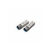
HFCT-5953TL Avago Technologies US Inc., HFCT-5953TL Datasheet - Page 11

HFCT-5953TL
Manufacturer Part Number
HFCT-5953TL
Description
Fiber Optic Transmitters, Receivers, Transceivers OC12 IR 2x5 SFF LC
Manufacturer
Avago Technologies US Inc.
Datasheet
1.HFCT-5953TL.pdf
(17 pages)
Specifications of HFCT-5953TL
Function
High performance, modules for serial optical data communication applications, designed for single mode fiber.
Product
Transceiver
Data Rate
622 Mbps
Wavelength
1300 nm
Maximum Rise Time
1 ns, 0.5 ns
Maximum Fall Time
1 ns, 0.5 ns
Maximum Output Current
50 mA
Operating Supply Voltage
3.14 V to 3.47 V
Maximum Operating Temperature
+ 70 C
Minimum Operating Temperature
0 C
Package / Case
DIP-10 with Connector
Optical Fiber Type
TX/RX
Data Transfer Rate
622Mbps
Optical Rise Time
1/0.5ns
Optical Fall Time
1/0.5ns
Operating Temperature Classification
Commercial
Peak Wavelength
1356/1570nm
Package Type
DIP With Connector
Operating Supply Voltage (min)
3.14V
Operating Supply Voltage (typ)
3.3V
Operating Supply Voltage (max)
3.47V
Output Current
50mA
Operating Temp Range
0C to 70C
Mounting
Snap Fit To Panel
Pin Count
10
For Use With
Singlemode Glass
Lead Free Status / RoHS Status
Lead free / RoHS Compliant
Electromagnetic Interference (EMI)
One of a circuit board designer’s foremost concerns is
the control of electromagnetic emissions from electronic
equipment. Success in controlling generated Electromag-
netic Interference (EMI) enables the designer to pass a
governmental agency’s EMI regulatory standard and more
importantly, it reduces the possibility of interference to
neighboring equipment. Avago Technologies has de-
signed the HFCT-5953xxx/HFCT-5954xxx to provide excel-
lent EMI performance. The EMI performance of a chassis
is dependent on physical design and features which help
improve EMI suppression. Avago Technologies encour-
ages using standard RF suppression practices and avoiding
poorly EMI-sealed enclosures.
Avago Technologies’ HFCT-5953ATL/TL/HFCT-5954ATL/
TL OC-12/STM-4 LC transceivers have nose shields which
provide a convenient chassis connection to the nose of
the transceiver. This nose shield improves system EMI
performance by closing off the LC aperture. Localized
shielding is also improved by tying the four metal hous-
ing package grounding tabs to signal ground on the
PCB. Though not obvious by inspection, the nose
shield and metal housing are electrically separated for
customers who do not wish to directly tie chassis and
signal grounds together. Figure 10 shows the recom-
mended positioning of the transceivers with respect to
the PCB and faceplate.
11
(0.4 ±0.004)
DIMENSIONS IN MILLIMETERS (INCHES)
1.
2.
Figure 10 - Recommended Panel Mounting
10.16 ±0.1
FIGURE DESCRIBES THE RECOMMENDED FRONT PANEL OPENING FOR A LC OR SG SFF TRANSCEIVER.
SFF TRANSCEIVER PLACED AT 15.24 mm (0.6) MIN. SPACING.
(0.56 ±0.004)
14.22 ±0.1
DETAIL A
15.24
(0.6)
TOP OF PCB
15.24
(0.6)
B
(0.039)
(0.62 MAX. 0.59 MIN.)
15.75 MAX. 15.0 MIN.
1
A
SECTION B - B
SOLDER POSTS
Package and Handling Instructions
Flammability
The HFCT-5953xxx/HFCT-5954xxx transceivers housing
consist of high strength, heat resistant and UL 94 V-0
flame retardant plastic and metal packaging.
Recommended Solder and Wash Process
The HFCT-5953xxx/HFCT-5954xxx are compatible with
industry-standard wave processes.
Process plug
The transceivers are supplied with a process plug for
protection of the optical port within the LC connector
receptacle. This process plug prevents contamination
during wave solder and aqueous rinse as well as during
handling, shipping and storage. It is made of a high-
temperature, molded sealing material.
Recommended Solder fluxes
Solder fluxes used with theHFCT-5953xxx/HFCT-
5954xxx should be water-soluble, organic fluxes. Rec-
ommended solder fluxes include Lonco 3355-11 from
London Chemical West, Inc. of Burbank, CA, and 100
Flux from Alpha-Metals of Jersey City, NJ.
B


