210-433FR1 RF Solutions, 210-433FR1 Datasheet
210-433FR1
Specifications of 210-433FR1


Related parts for 210-433FR1


210-433FR1 Summary of contents
Page 1
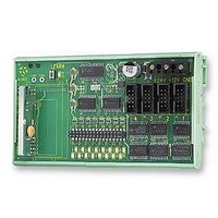
... DIN Rail mounting Telemetry Module. The 210Rx Module performs the RF reception and decoding. It has 16 outputs. Any combination of the Output Modules below may be connected to the 210Rx module to utilise the full 16 outputs. Output module 215 provides 8 relay outputs rate 3A at 230Vac Output module 216 provides 4 relay outputs rate 5A ...
Page 2
... Volt Free contact Inputs via Screw Terminals 12 / 24Vdc Supply Range; 433MHz Upto 200 Metres 458MHz Upto 4,000 Metres High Security RF Protocol Auto Transmit Mode Automatic Watchdog Transmission 204 Hand Held Transmitter Pocket Fob with Wall Mounting Holster 4, 8 And 16 Switch Versions ...
Page 3
... Operating the 210Rx with a ‘200 series Transmitter Each 200Tx has a unique identity (factory set) which must be learnt by the 210Rx. The 200Tx has 8 inputs which are automatically mapped to the 210Rx as either outputs 1-8 or 9-15 according to the OPT3 jumper link on the 200Tx.as below 200Tx Jumper Link OPT3 Auto Transmit with Watchdog Mode ‘ ...
Page 4
... R Connecting an Antenna The 210Rx has a 300mm flying lead cable (50ohm) with a panel mount BNC socket provided to mount on an enclosure. This cable may be extended however please note that typically there is a 50% range reduction with every 3metres of coax cable used! For increasing range performance a +3dB gain antenna is available. This is supplied with wall mounting bracket and 2metres of coax cable, it plugs in directly to the 210Rx BNC connector ...
Page 5
... Channel Phase Controlled Dimming Outputs Connects Directly to 210 Module Description The 210Rx module performs the RF reception and decoding. It has 16 available outputs arranged easy plug in connectors. From these connectors any one or combination of output modules may be connected (connecting leads supplied) to use some or all of the 16 available outputs. ...
Page 6
... Configuration is now complete and now the transmitter unit can be learned to the receiver. Each time power is applied the 210Rx will now show the mode it is configured to for the first 5 seconds. In the event that no configuration has taken place then on power up LED's 1-16 will flash alternately. ...
Page 7
... Decide which switch on the Transmitter is to operate which output channel on the 210 Receiver decoder. 2. Select the 210Rx output channel by briefly pressing the 210 Rx learn switch (All LEDs flash briefly) until the desired channel is selected (1 thro 16). The 210 Rx LED indicates the currently selected output channel. ...
Page 8
... Apply power and the output LEDs will operate alternately 1 –16 and then repeat. 4. Depress and release the learn button twice. 5. The 210Rx will then enter the time set mode where the timing pots for channels 1, 2 and 3 can be set. Initially LED1 will illuminate. This is to indicate that output 1 timer set. Pressing the learn switch will allow the user to cycle through the three timed outputs ...
Page 9
... For further information see the 200 Series Transmitter Module description, above. Connecting an Antenna The 210Rx has a 300mm flying lead cable (50ohm) with a panel mount BNC socket provided to mount on an enclosure. This cable may be extended however please note that typically there is a 50% range reduction with every 3metres of coax cable used! For increasing range performance a +3dB gain antenna is available ...
Page 10
... Logic High Part Numbering Part No 210-433R1 Receiver Decoder 16 Channels DIN Rail Mounting Module 433MHz 210-458R1 Receiver Decoder 16 Channels DIN Rail Mounting Module 458MHz PSU12V1AIN Power Supply Unit 110-240Vac input, 12V 1A output ENC Enclosure UP67, with internal mounting plate and DIN Rail. ...
Page 11
... Open 200Tx O ©2002 Reg. No. 227 4001, England C ONTROL 210Rx Outputs 9-15 Outputs 9-15 From 200Tx I/P1-7 Ouput 16 System Fail Output 210Rx Outputs 1-8 Outputs 9-15 Ouput 16 Outputs 4-15 From 200Tx Output 16 System Watchdog** Page 11 Output 1 From 200Tx A Output 2 From 200Tx B Output 3 ...
Page 12
... R ‘215’ 8 Relay output Module 210 Rx This DIN Rail module connects directly to any of the 210Rx output connectors and provides; 8 relay switches rated 230Vac at 3A The only connections required are Connection to the 210 Receiver via the ribbon cable supplied. Connection to each relay via screw terminals provided. ...
Page 13
... The only connections required are Connection to the 210 Receiver via the ribbon cable supplied. Connection to each relay output via screw terminals provided. The module requires no other connections as power is supplied from the 210Rx module. Technical Specifications Dimensions: Within DIN Rail : 135 Storage Temperature ...
Page 14
... This DIN Rail module provides four dimming outputs rated 240 Vac at 2.5A continuous. Connection to the 210Rx module is by the lead supplied. This module may be connected to any of the 210 receiver’s output plugs (marked as 1 – 4). However please note that the relevant 210 receiver outputs must be set to momentary operation without any time delay. ...