TCLT1007 Vishay, TCLT1007 Datasheet
TCLT1007
Specifications of TCLT1007
Available stocks


Related parts for TCLT1007

TCLT1007 Summary of contents
Page 1
... CTR 50 - 600 %, SMD-4 TCLT1002 CTR 63 - 125 %, SMD-4 TCLT1003 CTR 100 - 200 %, SMD-4 TCLT1005 CTR 50 - 150 %, SMD-4 TCLT1006 CTR 100 - 300 %, SMD-4 TCLT1007 CTR 80 - 160 %, SMD-4 TCLT1008 CTR 130 - 260 %, SMD-4 TCLT1009 CTR 200 - 400 %, SMD-4 NOTE: Available only on tape and reel. V Remarks www ...
Page 2
... TCLT10.. Series Vishay Semiconductors Absolute Maximum Ratings °C, unless otherwise specified amb Stresses in excess of the absolute Maximum Ratings can cause permanent damage to the device. Functional operation of the device is not implied at these or any other conditions in excess of those given in the operational sections of this document. Exposure to absolute Maximum Rating for extended periods of the time can adversely affect reliability ...
Page 3
... CEsat = 10 mA Test condition Part = 5 mA TCLT1000 TCLT1002 F TCLT1003 = 1 mA TCLT1002 F TCLT1003 = 5 mA TCLT1005 F TCLT1006 TCLT1007 TCLT1008 TCLT1009 Test condition Symbol I F Test condition Symbol P diss Test condition Symbol V IOTM T si TCLT10.. Series Vishay Semiconductors Min Typ. Max 0.3 110 0.3 ...
Page 4
... TCLT10.. Series Vishay Semiconductors Insulation Rated Parameters Parameter Partial discharge test voltage - 100 %, t Routine test Partial discharge test voltage - Lot test (sample test) (see figure 2) Insulation resistance V = 500 500 500 (construction test only) 300 Phototransistor 250 Psi ( mW ) 200 150 100 IR-Diode ...
Page 5
... 100% input amplitude 90% 10% 0 Oscilloscope Fig. 5 Switching Times Oscilloscope Ω ≥ ≤ TCLT10.. Series Vishay Semiconductors Min Typ. Max 3.0 3.0 6.0 0.3 4.7 5.0 9.0 10.0 96 11698 off on pulse duration t storage time s delay time t fall time f rise time turn-off time ...
Page 6
... TCLT10.. Series Vishay Semiconductors Typical Characteristics (T 300 Coupled device 250 200 Phototransistor 150 IR-diode 100 – Ambient T emperature( ° 1700 amb Fig. 6 Total Power Dissipation vs. Ambient Temperature 1000.0 100.0 10.0 1.0 0.1 0.0 0.2 0.4 0.6 0.8 1.0 1.2 1.4 1.6 1.8 2.0 ...
Page 7
... I – Collector Current ( 11030 C Fig. 14 Turn on / off Time vs. Collector Current Document Number 83515 Rev. 1.7, 20-Apr-04 50 Saturated Operation 100 0 95 11031 Fig. 15 Turn on / off Time vs. Forward Current 100 10 TCLT10.. Series Vishay Semiconductors =5V =1k Ω t off – Forward Current ( www.vishay.com 7 ...
Page 8
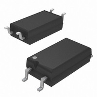
... TCLT10.. Series Vishay Semiconductors Package Dimensions in mm www.vishay.com 8 VISHAY 15243 Document Number 83515 Rev. 1.7, 20-Apr-04 ...
Page 9
... Various national and international initiatives are pressing for an earlier ban on these substances. Vishay Semiconductor GmbH has been able to use its policy of continuous improvements to eliminate the use of ODSs listed in the following documents. 1. Annex A, B and list of transitional substances of the Montreal Protocol and the London Amendments respectively 2 ...