SFH608-4 Vishay, SFH608-4 Datasheet
SFH608-4
Specifications of SFH608-4
Available stocks


Related parts for SFH608-4

SFH608-4 Summary of contents
Page 1
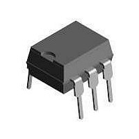
... This makes the device ideal for low current switching applications. The SFH608 is packaged in a six pin plastic DIP. Order Information Part SFH608-2 SFH608-3 SFH608-4 SFH608-5 SFH608-2-X006 SFH608-2-X007 SFH608-2-X009 SFH608-3-X006 SFH608-3-X007 SFH608-4-X006 SFH608-4-X007 SFH608-5-X007 For additional information on the available options refer to Option Information. SFH608 Vishay Semiconductors ...
Page 2
... SFH608 Vishay Semiconductors Absolute Maximum Ratings °C, unless otherwise specified amb Stresses in excess of the absolute Maximum Ratings can cause permanent damage to the device. Functional operation of the device is not implied at these or any other conditions in excess of those given in the operational sections of this document. Exposure to absolute Maximum Rating for extended periods of the time can adversely affect reliability ...
Page 3
... SFH608 1.0 mA SFH608 1.0 mA SFH608 Test condition Part Symbol = 0.5 V SFH608 1.5 V SFH608 0.5 V SFH608 1.5 V SFH608 0.5 V SFH608 1.5 V SFH608 0.5 V SFH608 1.5 V SFH608-5 CE SFH608 Vishay Semiconductors Min Typ. Max 1.1 1.5 6.0 0. 1070 Min Typ. Max 55 7 500 10 200 Min Typ ...
Page 4
... Figure 2. Switching Times www.vishay.com 4 Test condition Symbol ), 5 5 off = 5 5 isfh608_03 Figure 3. Current Transfer Ratio (typ.) isfh608_04 Figure 4. Current Transfer Ratio (typ.) Min Typ. Max 8.0 5.0 7 Document Number 83664 Rev. 1.4, 26-Oct-04 Unit µs µs µs µs ...
Page 5
... 1.0 mA isfh608_06 Figure 6. Diode Forward Voltage (typ isfh608_07 Figure 7. Output Characteristics Document Number 83664 Rev. 1.4, 26-Oct-04 Vishay Semiconductors isfh608_08 Figure 8. Output Characteristics isfh608_09 Figure 9. Permissible Forward Current Diode P tot = isfh608_10 Figure 10. Permissible Power Dissipation for Transistor and Diode SFH608 www.vishay.com 5 ...
Page 6
... Min. 4° typ. .018 (0.45) .022 (0.55) i178004 www.vishay.com 6 isfh608_12 Figure 12. Collector-Emitter Leakage Current vs.Temp. pin one ISO Method .300 (7.62) .048 (0.45) typ. .022 (0.55) .130 (3.30) .150 (3.81) 18° ...
Page 7
... TYP . .180 (4.6) .160 (4.1) .0040 (.102) .0098 (.249) .315 (8.0) MIN. .331 (8.4) MIN. .406 (10.3) MAX. SFH608 Vishay Semiconductors Option 9 .375 (9.53) .395 (10.03) .300 (7.62) ref. .012 (.30) typ. .020 (.51) .040 (1.02) 15° max. .315 (8.00) min. ...
Page 8
... SFH608 Vishay Semiconductors Ozone Depleting Substances Policy Statement It is the policy of Vishay Semiconductor GmbH to 1. Meet all present and future national and international statutory requirements. 2. Regularly and continuously improve the performance of our products, processes, distribution and operatingsystems with respect to their impact on the health and safety of our employees and the public, as well as their impact on the environment ...
Page 9
... Information contained herein is intended to provide a product description only. No license, express or implied, by estoppel or otherwise, to any intellectual property rights is granted by this document. Except as provided in Vishay's terms and conditions of sale for such products, Vishay assumes no liability whatsoever, and disclaims any express or implied warranty, relating to sale and/or use of Vishay products including liability or warranties relating to fitness for a particular purpose, merchantability, or infringement of any patent, copyright, or other intellectual property right ...