VS-10RIA120 Vishay, VS-10RIA120 Datasheet - Page 4
VS-10RIA120
Manufacturer Part Number
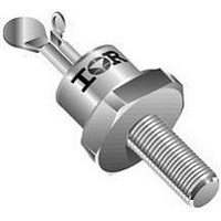
VS-10RIA120
Description
SCR THYRISTOR, 10A, 1.2KV, TO-208AA
Manufacturer
Vishay
Datasheet
1.VS-10RIA120.pdf
(8 pages)
Specifications of VS-10RIA120
Peak Repetitive Off-state Voltage, Vdrm
1.2kV
Gate Trigger Current Max, Igt
60mA
Current It Av
10A
On State Rms Current It(rms)
25A
Peak Non Rep Surge Current Itsm 50hz
225A
Lead Free Status / RoHS Status
Lead free / RoHS Compliant


10RIA Series
Vishay High Power Products
Note
• The table above shows the increment of thermal resistance R
www.vishay.com
4
THERMAL AND MECHANICAL SPECIFICATIONS
PARAMETER
Maximum operating junction
and storage temperature range
Maximum thermal resistance,
junction to case
Maximum thermal resistance,
case to heatsink
Mounting torque
Approximate weight
Case style
ΔR
CONDUCTION ANGLE
thJC
CONDUCTION
180°
120°
130
120
110
100
90°
60°
30°
90
80
70
60
50
40
0
Fig. 1 - Current Ratings Characteristics
2
Average On-state Current (A)
4
30°
10RIA Series
R
thJC
6
60°
SINUSOIDAL CONDUCTION
(DC) = 1.85 K/W
8
90°
10 12 14 16 18
SYMBOL
Conduction Angle
120°
T
For technical questions, contact: ind-modules@vishay.com
R
R
J
, T
thCS
thJC
0.44
0.53
0.68
1.01
1.71
Stg
180°
Medium Power Thyristors
DC operation
Mounting surface, smooth, flat and greased
Lubricated threads
(Non-lubricated threads)
See dimensions - link at the end of datasheet
(Stud Version), 10 A
thJC
TEST CONDITIONS
RECTANGULAR CONDUCTION
when devices operate at different conduction angles than DC
0.32
0.56
0.75
1.05
1.73
130
120
110
100
90
80
70
60
50
40
0
Fig. 2 - Current Ratings Characteristics
30°
5
Average On-state Current (A)
60°
0.23 (0.32)
20 (27.5)
10RIA Series
R
TO NUT
2.3 (3.1)
10
TEST CONDITIONS
thJC
90°
T
J
120°
= T
- 65 to 125
(DC) = 1.85 K/W
VALUES
15
TO-208AA (TO-48)
1.85
0.35
0.49
J
180°
14
maximum
TO DEVICE
Conduction Period
Document Number: 93689
20
0.29
DC
2.8
25
Revision: 06-Jun-08
25
30
UNITS
kgf · m
UNITS
lbf ⋅ in
N · m
K/W
K/W
oz.
°C
g
Related parts for VS-10RIA120
Image
Part Number
Description
Manufacturer
Datasheet
Request
R

Part Number:
Description:
Power Relay 1 Pole - 15a Vs-nr Series
Manufacturer:
Fujitsu Microelectronics, Inc.
Datasheet:

Part Number:
Description:
Schottky Diodes & Rectifiers 1.0 Amp 60 Volt
Manufacturer:
Vishay Semiconductors
Datasheet:
Part Number:
Description:
Schottky Diodes & Rectifiers 1.0 Amp 50 Volt
Manufacturer:
Vishay Semiconductors
Datasheet:

Part Number:
Description:
Rectifiers 8A 600V Hyperfast 22ns TO-220AC
Manufacturer:
Vishay
Datasheet:
Part Number:
Description:
Rectifiers 8A 600V Hyperfast Vf 1V TO-220AC
Manufacturer:
Vishay
Datasheet:
Part Number:
Description:
Rectifiers 8A 600V Hyperfast 22nsTO-220AC Ha Free
Manufacturer:
Vishay
Datasheet:

Part Number:
Description:
Rectifiers 8A 600V Hyperfast Vf 1V TO-220FPAC
Manufacturer:
Vishay
Datasheet:
Part Number:
Description:
Rectifiers 8A 600V Hyperfast 16ns TO-220FPAC
Manufacturer:
Vishay
Datasheet:
Part Number:
Description:
Rectifiers 8A 600V Hyperfast 22ns TO-220FPAC
Manufacturer:
Vishay
Datasheet:
Part Number:
Description:
Rectifiers 8A 600V Hyperfast 16ns TO-220AC
Manufacturer:
Vishay
Datasheet:

Part Number:
Description:
BRIDGE RECTIFIER, 25A, 1000V
Manufacturer:
Vishay
Datasheet:

Part Number:
Description:
SCHOTTKY RECTIFIER, 1A, 30V, SMB
Manufacturer:
Vishay
Datasheet:

Part Number:
Description:
SCHOTTKY RECTIFIER, 1A 20V DO-204AL
Manufacturer:
Vishay
Datasheet:

Part Number:
Description:
SCHOTTKY RECTIFIER, 1A, 15V, SMB
Manufacturer:
Vishay
Datasheet:
Part Number:
Description:
SCHOTTKY RECTIFIER, 1A, 40V, SMB
Manufacturer:
Vishay
Datasheet: