PM25CL1A120 Powerex Inc, PM25CL1A120 Datasheet - Page 2
PM25CL1A120
Manufacturer Part Number
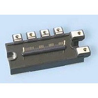
PM25CL1A120
Description
IGBT MODULE, 1.2KV, 25A
Manufacturer
Powerex Inc
Datasheet
1.PM25CL1A120.pdf
(5 pages)
Specifications of PM25CL1A120
Dc Collector Current
25A
Collector Emitter Voltage Vces
1.2kV
Power Dissipation Pd
128W
Collector Emitter Voltage V(br)ceo
1.2kV
Operating Temperature Range
-20°C To +150°C
No. Of Pins
25
Voltage
1200V
Current
25A
Circuit Configuration
6-Pac
Package
120x55mm - A
Rohs Compliant
Yes
Recommended Accessory
BP7B-LB
Lead Free Status / RoHS Status
Lead free / RoHS Compliant
Available stocks
Company
Part Number
Manufacturer
Quantity
Price
Company:

Part Number:
PM25CL1A120
Manufacturer:
MITSUBISH
Quantity:
1 000


2
Powerex, Inc., 173 Pavilion Lane, Youngwood, Pennsylvania 15697 (724) 925-7272 www.pwrx.com
PM25CL1A120
Intellimod™ L1-Series
Three Phase IGBT Inverter
25 Amperes/1200 Volts
Absolute Maximum Ratings, T
Characteristics
Power Device Junction Temperature
Storage Temperature
Mounting Torque, M5 Mounting Screws
Mounting Torque, M5 Main Terminal Screws
Module Weight (Typical)
Supply Voltage, Surge (Applied between P - N)
Supply Voltage Protected by Short Circuit Protection Capability*
Isolation Voltage, AC 1 minute, 60Hz Sinusoidal
IGBT Inverter Sector
Collector-Emitter Voltage (V
Collector Current (T
Peak Collector Current (T
Collector Dissipation (T
Control Sector
Supply Voltage (Applied between V
Input Voltage (Applied between U
Fault Output Supply Voltage
(Applied between U
Fault Output Current (Sink Current at U
Electrical and Mechanical Characteristics, T
Characteristics
IGBT Inverter Sector
Collector-Emitter Saturation Voltage
Diode Forward Voltage
Inductive Load Switching Times
Collector-Emitter Cutoff Current
*VD = 13.5 ~ 16.5V, Inverter Part, T
C
FO
= 25°C) (Note 1)
-V
C
UPC
C
= 25°C) (Note 1)
j
= 125°C
D
= 25°C)
, V
= 15V, V
FO
P
-V
-V
UP1
VPC
UPC
CIN
-V
FO
j
, W
UPC
= 25°C unless otherwise specified
, V
= 15V)
, V
P
FO
FO
-V
, V
V
-V
, W
VPC
Symbol
VP1
t
CE(sat)
t
I
C(on)
C(off)
V
CES
WPC
t
t
t
on
EC
off
FO
rr
-V
, W
, F
VPC
, F
P
-V
O
O
, V
Terminals)
WPC
-V
j
= 25°C unless otherwise specified
WP1
NC
, U
)
V
-V
V
-I
CE
N
V
V
CE
C
WPC
- V
D
D
V
= 25A, V
= V
= 15V, V
= 15V, V
D
= V
N
V
- W
, V
= 15V, V
CC
CES
CES
Test Conditions
N1
N
= 600V, I
T
T
, V
-V
-V
T
, V
CIN
j
j
CIN
CIN
j
= 125°C
= 125°C
NC
D
NC
= 25°C
D
CIN
= 15V, T
= 15V, V
)
)
= 0V, I
= 0V, I
= 15V, T
= 0 ↔ 15V
C
= 25A
V
V
C
C
CC(surge)
Symbol
CC(prot.)
D
j
j
V
= 25A,
= 25A,
V
±I
V
T
V
= 125°C
±I
I
= 25°C
CES
P
V
—
—
—
CIN
FO
= 15V
T
ISO
stg
FO
CP
C
D
C
j
Min.
0.3
—
—
—
—
—
—
—
—
—
PM25CL1A120
-20 to 150
-40 to 125
1000
2500
1200
380
800
128
31
31
25
50
20
20
20
20
1.65
1.85
Typ.
2.3
0.8
0.3
0.4
0.4
1.2
—
—
Max.
2.35
2.15
3.3
2.0
0.8
2.8
1.0
1.2
1.0
10
Amperes
Amperes
03/10 Rev. 1
Grams
Watts
Volts
Volts
Units
Volts
Volts
Volts
Volts
Volts
in-lb
in-lb
mA
°C
°C
Volts
Volts
Volts
Units
mA
mA
µs
µs
µs
µs
µs
Related parts for PM25CL1A120
Image
Part Number
Description
Manufacturer
Datasheet
Request
R

Part Number:
Description:
Power Module Power Modules Standard Power - Switchbox Ac/dc . Switchbox Pm25 Series Dc-dc Converter
Manufacturer:
Powerbox
Datasheet:
Part Number:
Description:
25-28 WATTS SINGLE & MULTIPLE OUTPUT AC/DC MEDICAL
Manufacturer:
POWERBOX [Powerbox]
Datasheet:

Part Number:
Description:
Manufacturer:
Powerex Inc
Datasheet:
Part Number:
Description:
Manufacturer:
Powerex Inc
Datasheet:
Part Number:
Description:
Manufacturer:
Powerex Inc
Datasheet:
Part Number:
Description:
Manufacturer:
Powerex Inc
Datasheet:
Part Number:
Description:
Manufacturer:
Powerex Inc
Datasheet:
Part Number:
Description:
Manufacturer:
Powerex Inc
Datasheet:
Part Number:
Description:
Manufacturer:
Powerex Inc
Datasheet:
Part Number:
Description:
Manufacturer:
Powerex Inc
Datasheet:
Part Number:
Description:
Manufacturer:
Powerex Inc
Datasheet:
Part Number:
Description:
Manufacturer:
Powerex Inc
Datasheet:
Part Number:
Description:
Manufacturer:
Powerex Inc
Datasheet:
Part Number:
Description:
Manufacturer:
Powerex Inc
Datasheet: