XCS-PA792 TELEMECANIQUE, XCS-PA792 Datasheet - Page 2
XCS-PA792
Manufacturer Part Number
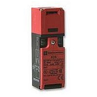
XCS-PA792
Description
SAFETY SWITCH, 2NC
Manufacturer
TELEMECANIQUE
Datasheet
1.XCS-PA792.pdf
(12 pages)
Specifications of XCS-PA792
Contact Voltage Ac Max
250V
Contact Voltage Dc Max
24V
Contact Current Ac Max
6A
Contact Current Dc Max
540mA
Switch Terminals
Cage Clamp / Screw
Approval Bodies
EN1088, EN60204, EN60947-5-1


Environment
Limit switch type
Conforming
to standards
Product certifications
Protective treatment
Ambient air temperature
Vibration resistance
Shock resistance
Electric shock protection
Degree of protection
Cable entry
(Country specific references)
Contact block characteristics
Rated operational characteristics
Rated thermal current in enclosure
Rated insulation voltage
Rated impulse withstand voltage
Positive operation
Resistance across terminals
Short-circuit protection
Cabling
Electrical durability
a.c. supply c 50/60 Hz
p inductive circuit
d.c. supply a
Products
Machine assemblies
Components for safety applications
Guard switches
Metal, turret head, types XCS-A, XCS-C and XCS-E
Double insulated, turret head, types XCS-PA, XCS-TA and XCS-TE
General characteristics
(1) Live parts of the switches are protected against the penetration of dust and water. However, when installing take all
necessary precautions to prevent the penetration of solid bodies, or liquids with a high dust content, into the actuator
aperture. Not recommended for use in saline atmospheres.
XCS-A, XCS-C, XCS-E (metal case)
IEC 947-5-1, EN 60 947-5-1, UL 508, CSA C22-2 n 14, JIS C4520
IEC 204-1, EN 60 204-1, EN 1088, EN 292
UL, CSA, BG
Standard version : “TC”
Operation : - 25…+ 70 C (- 25…+ 40 C for XCS-E and - 25…+ 60 C for XCS-TE)
Storage : - 40…+ 70 C
5 gn (10…500 Hz) conforming to IEC 68-2-6
10 gn (duration 11 ms) conforming to IEC 68-2-27
Class I conforming to IEC 536
IP 67 conforming to IEC 529 (1) and IEC 947-5-1
1 entry (XCS-A and XCS-E) or 2 entries
(XCS-E) tapped for Pg 13.5 (n 13) cable
gland, tapped M20 or tapped 1/2" NPT
XCS-A, XCS-C, XCS-PA, XCS-TA : c
XCS-E, XCS-TE : c
All models : a a a a a DC-13, Q300 : Ue = 250 V, Ie = 0.27 A or Ue = 125 V, Ie = 0.54 A
conforming to IEC 947-5-1, EN 60 947-5-1
XCS-A, XCS-C, XCS-PA, XCS-TA : Ithe = 10 A
XCS-E, XCS-TE : Ithe = 6 A
Ui = 500 V conforming to IEC 947-5-1
Ui = 300 V conforming to UL 508, CSA C22-2 n 14
XCS-A, XCS-C, XCS-PA, XCS-TA : Uimp = 6 kV conforming to IEC 947-5-1
XCS-E, XCS-TE : Uimp = 4 kV conforming to IEC 947-5-1
N/C contact with positive opening operation conforming to IEC 947-5-1 Section 3, EN 60 947-5-1
10 A cartridge fuse type gG (gl)
Screw clamp terminals. Clamping capacity, min. : 1 x 0.5 mm
Conforming to IEC 947-5-1 Appendix C.
Utilisation categories AC-15 and DC-13.
Maximum operating rate : 3600 operating cycles per hour.
Load factor : 0.5
Power broken in W for 1 million operating cycles
Voltage
p
30 m conforming to IEC 957-5-4
0,5
0,2
0,1
1
0,5
1
V
W
230 V
c c
c c AC-15, B300 : Ue = 240 V, Ie = 1.5 A or Ue = 120 V, Ie = 3 A
2
3 4 5
110 V
12/24/48 V
24
13
Current in A
10
c c
c c AC-15, A300 : Ue = 240 V, Ie = 3 A or Ue = 120 V, Ie = 6 A
48
9
XCS-PA, XCS-TA, XCS-TE (double insulated case)
UL, CSA, BG (pending)
Class 2 conforming to IEC 536
1 entry (XCS-PA and XCS-TE) or 2 entries (XCS-TA) tapped for Pg 11
(n 11) cable gland, tapped M16 or tapped 1/2" NPT (with adaptor) for
XCS-TA and XCS-TE
120
7
2
, max. : 2 x 1.5 mm
2
with or without cable end
Te
2/15
2
Related parts for XCS-PA792
Image
Part Number
Description
Manufacturer
Datasheet
Request
R


Part Number:
Description:
Control Contactor
Manufacturer:
TELEMECANIQUE
Datasheet:

Part Number:
Description:
Control Contactor
Manufacturer:
TELEMECANIQUE
Datasheet:

Part Number:
Description:
Contactor
Manufacturer:
TELEMECANIQUE
Datasheet:

Part Number:
Description:
Contactor
Manufacturer:
TELEMECANIQUE
Datasheet:
Part Number:
Description:
Control Contactor
Manufacturer:
TELEMECANIQUE
Datasheet:

Part Number:
Description:
CONTACTOR, 2NO/2NC, 9A, 230VAC
Manufacturer:
TELEMECANIQUE
Datasheet:

Part Number:
Description:
Contactor
Manufacturer:
TELEMECANIQUE
Datasheet:

Part Number:
Description:
CONTACTOR, 4KW, 400VAC
Manufacturer:
TELEMECANIQUE
Datasheet:

Part Number:
Description:
PILOT LIGHT HEAD, WHITE
Manufacturer:
TELEMECANIQUE
Datasheet:

Part Number:
Description:
LENS HEAD, BA 9S
Manufacturer:
TELEMECANIQUE
Datasheet:
Part Number:
Description:
LENS HEAD, BA 9S
Manufacturer:
TELEMECANIQUE
Datasheet:

Part Number:
Description:
LED BODY, 24V
Manufacturer:
TELEMECANIQUE
Datasheet:
Part Number:
Description:
LED BODY, 48V
Manufacturer:
TELEMECANIQUE
Datasheet: