P1-25/I2H/SVB+K-CI MOELLER, P1-25/I2H/SVB+K-CI Datasheet - Page 7
P1-25/I2H/SVB+K-CI
Manufacturer Part Number
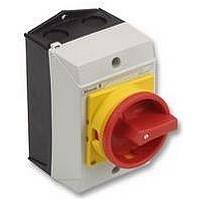
P1-25/I2H/SVB+K-CI
Description
ISOLATOR, PLASTIC, ENCL, 25A, 3POLE
Manufacturer
MOELLER
Series
P1r
Datasheet
1.P1-25I2HSVBK-CI.pdf
(10 pages)
Specifications of P1-25/I2H/SVB+K-CI
No. Of Poles
3
Contact Voltage Ac Max
690V
Contact Current Ac Max
25A
Svhc
No SVHC (18-Jun-2010)
Current Rating
25A
Power Rating
13kW
Switching Ac3 Power Max
13kW
Voltage
RoHS Compliant


Switchover with rotary switch T
Further typical applications for the rotary switch T are for example:
• the star-delta starting circuit for three-phase motors, with and without change of
• the speed changeover of three-phase motors for two, three, four speeds with and
• the mains switchover of the mains circuit and the back up generator supply on one
• the step circuit for any load with and without off position
• the ammeter switchover for direct measurement or via current transformer
Screening connection to the switch enclosure!
The actuation of three-phase motors is implemented more and more frequently via
electronic speed encoders. The motor cable is screened in order to comply with the
EMC guidelines. We can provide a mounting plate screen for simple and fast
application of the screen with a maintenance and manual override switch.
CI-K the clever enclosure
The enclosure CI-K has a unique combination: plastic insulated housing with flexible
push-through diaphragm for main and control cables. Enclosure sizes I1 and I2
provide faster connection from above, below or from the rear. The sizes I3 to I5
provide the push-through diaphragm for the control cables.
Safety switch with load shedding and signalling
The safety switches P and T are functionally designed as maintenance and manual
override switches. Safe isolation of a load from the mains is the primary function.
The switch can be loaded with rated uninterrupted current I
shedding circuit. The switch switches without a load! The additional signalling
contacts can be used for indicating the switch position. The respective processing
and use in the application program of the system enhances safety.
direction as well as contactor interlocking circuits
without direction of reversal rotation
or more loads
u
due to the load
P1 = on
P2 = off
Q11 = load shedding
Q11
L1
L2
L3
N
Q1
F2
F1
1
2
1
2
U
3
M
3
4
3
4
V
5
6
5
6
W
P1
7
8
P2
9
10
F0
Q11
F2
O
I
95
96
21
22
13
14
11
12
A1
A2
A2
Q11
13
14
5
Related parts for P1-25/I2H/SVB+K-CI
Image
Part Number
Description
Manufacturer
Datasheet
Request
R

Part Number:
Description:
25A DISCONNECT SWITCH, BLK, HNDL IN ATEX ENCLOSURE
Manufacturer:
MOELLER

Part Number:
Description:
SWITCH HEAD E/P / R-ATO HEAD (0043065) MOELLER
Manufacturer:
MOELLER

Part Number:
Description:
BASIC UNIT, PLASTIC, 1N0/1NC, IP66
Manufacturer:
MOELLER
Datasheet:


Part Number:
Description:
FRONT FIXING, LED, 85-264VAC, BLUE
Manufacturer:
MOELLER
Datasheet:

Part Number:
Description:
REAR FIXING, LED, 18-30VAC/DC, GRN
Manufacturer:
MOELLER
Datasheet:
Part Number:
Description:
REAR FIXING, LED, 18-30VAC/DC, RED
Manufacturer:
MOELLER
Datasheet:
Part Number:
Description:
REAR FIXING, LED, 18-30VAC/DC, WHT
Manufacturer:
MOELLER
Datasheet: