CCM04-1889LFT R102 C&K Components, CCM04-1889LFT R102 Datasheet - Page 9
CCM04-1889LFT R102
Manufacturer Part Number
CCM04-1889LFT R102
Description
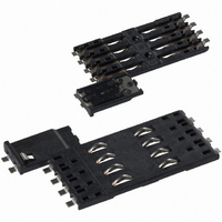
CONN SMART CARD LOW PRO 8PIN SMD
Manufacturer
C&K Components
Series
CCM04 MK IIr
Type
SIMr
Specifications of CCM04-1889LFT R102
Card Type
Smart Card
Number Of Positions
10 (8 + 2)
Connector Type
Connector
Insertion, Removal Method
Push In, Pull Out
Mounting Type
Surface Mount, Right Angle
Features
Switch
Height Above Board
0.083" (2.10mm)
Mounting Feature
Normal, Standard - Top
Contact Finish
Gold
Gender
M
Mounting Style
Surface Mount
Termination Method
Solder
Body Orientation
Straight
Contact Pitch (mm)
2.54mm
Housing Material
Thermoplastic
Number Of Contact Rows
2
Number Of Contacts
8POS
Current Rating (max)
1A
Contact Material
Copper Alloy
Operating Temp Range
-40C to 85C
Product Height (mm)
2.2mm
Product Depth (mm)
28mm
Product Length (mm)
16.2mm
Product
Card Connectors
Pitch
2.54 mm
Termination Style
Solder Tail
Number Of Rows
2
Current Rating
1 mA
Contact Plating
Gold
Lead Free Status / RoHS Status
Lead free / RoHS Compliant
Contact Finish Thickness
-
Ejector Side
-
Lead Free Status / RoHS Status
Not Compliant, Lead free / RoHS Compliant
Other names
401-1730-2
CCM04-1889 LFT
CCM04-1889LFT
Y1142-1889A LFT
CCM04-1889 LFT
CCM04-1889LFT
Y1142-1889A LFT


CCM03 MK II
A new range of CCM03 connectors
have been developed to interface with
SIM/SAM cards as defined by GSM11-
11 and ENV1375-1. The connectors are
available with either hinged covers or
fixed covers and have been designed to
minimize the amount of space needed
for PCB mounting.
Features
• Available with 6 or 8 contacts, with or
• Available with insulated card presence
• The cover springs open when
• The molding is polarized so that the
• The cover can be replaced without
• Inspection slots allow an electrical test
• The overall height of the connector is
• Available with 6 or 8 contacts.
• The overall height of the connector is
• With tape and reel packaging as stan-
• The high temperature thermoplastic
• By using an inlay finish in the contact
• Robustly formed printed circuit tails
without PCB locating pegs.
switch.
unlocked while the card is in place.
cover can only be closed if the card is
correctly inserted.
removing the connector from the PCB.
to be made without opening the cover.
only 2,5 mm. The amount of space
needed to mount the connector is just
29,65 mm x 17,2 mm.
2,85 mm max. Only 25,5 mm x 17,2
mm of board space is required to
mount the connector.
dard, the connectors are designed to
be automatically pick-and-placed.
moldings are suited for infrared and
convection soldering processes.
area the life of the precious metal is
extended by over 10 times that of
standard gold plating.
allow a co-planarity of ± 0,05 mm to
be maintained.
Hinged Cover
Fixed Cover
General
Contacts
Plating
Moldings
Slide lock/metal cover
Number of Contacts
Mechanical life, hinged cover
Mechanical life, fixed cover
Card insertion force
Card extraction force
Contact force
Slide locking force
Vibration
Shock
Insulation resistance
Resistance
Current rating
Dielectric strength
Card detection switch
Contact resistance
Dielectric strength
Current rating
Maximum power
Operating temperature
Soldering temperature
Damp heat
Salt mist
Quantity per reel, see table next page.
Contact Electrical Data
Packaging
Switch Electrical Data
Environmental Data
Construction
Mechanical Data
12
Copper alloy
Contact area : Gold alloy inlay or gold over nickel
Terminals : Tin lead (2µ min)
High temp. thermoplastic UL 94V-0 rated
Stainless steel
6 or 8
10,000 cycles min
50,000 cycles
Hinged cover: 1 N max
Fixed cover: 3 N max
Hinged cover: 1 N max
Fixed cover: 0.80 N min / 3 N max
0.25 N min / 0.50 N max
2 N min / 6 N max
Frequency 10 to 500 Hz. Acceleration 50m/s
Duration 6 hours - amplitude 0,35 mm
Max electrical discontinuity 1µs
Peak value 500 m/s
3 shocks in each direction of each axis
Max electrical discontinuity 1 µs
1,000 MΩ min
100 mΩ max
10 µA min / 1 A max
750 Vrms min
Normally open
100 mΩ max
250 Vrms min
1 mA min / 10m A max
0.2 VA
-40°C to +85°C
Temperature/time profile acc. to CECC00802
para. 6.1, Fig. 3 with peak temperature 250°C
IEC 512 test number 11c (10 days)
IEC 512 test number 11f (96 hours)
Specifications and dimensions subject to change
www.ck-components.com
2
– Duration 11 ms
Dimensions are shown in mm
2
Related parts for CCM04-1889LFT R102
Image
Part Number
Description
Manufacturer
Datasheet
Request
R

Part Number:
Description:
CONN SMART CARD LOW PRO 8PIN SMD
Manufacturer:
C&K Components
Datasheet:

Part Number:
Description:
Rotary Switches 4P 3 POS ROTARY SW
Manufacturer:
C&K Components
Part Number:
Description:
ANALOG ROCKER C&K DELTATECH
Manufacturer:
C&K Components

Part Number:
Description:
SWITCH MODULE SPST W/CAP L130
Manufacturer:
C&K Components
Datasheet:
Part Number:
Description:
SWITCH MODULE SPST W/CAP
Manufacturer:
C&K Components
Datasheet:

Part Number:
Description:
SWITCH MODULE DPST W/CAP L130
Manufacturer:
C&K Components
Datasheet:
Part Number:
Description:
SWITCH MOD DPST W/CAP L130 PU PO
Manufacturer:
C&K Components
Datasheet:
Part Number:
Description:
SWITCH MODULE DPST W/CAP L130
Manufacturer:
C&K Components
Datasheet:
Part Number:
Description:
SWITCH MOD DPST W/CAP L130 PO PU
Manufacturer:
C&K Components
Datasheet:
Part Number:
Description:
SWITCH MOD DPST W/CAP L130 PL PR
Manufacturer:
C&K Components
Datasheet:

Part Number:
Description:
SWITCH PB SQUARE WHT MOM SPST NO
Manufacturer:
C&K Components
Datasheet:
Part Number:
Description:
SWITCH PB SQUARE GRY MOM SPST NO
Manufacturer:
C&K Components
Datasheet:

Part Number:
Description:
SWITCH PB SQUARE RED MOM SPST NO
Manufacturer:
C&K Components
Datasheet: