E2AM12KS04M1C1 Omron, E2AM12KS04M1C1 Datasheet - Page 18
E2AM12KS04M1C1
Manufacturer Part Number
E2AM12KS04M1C1
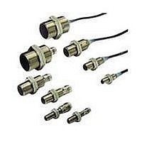
Description
Inductive Proximity Sensor
Manufacturer
Omron
Specifications of E2AM12KS04M1C1
Sensing Range
4mm
Supply Voltage Range Dc
12V To 24V
Circuitry
SPST-NO
Mounting Type
M12
Switch Terminals
Connector
Sensing Face Diameter
12mm
Supply Voltage Min
12VDC
Sensor Output
NPN
Svhc
No SVHC (15-Dec-2010)
Frequency Response Max
1000Hz
Length
48mm
Output Type
NPN
Sensing Range Max
4mm
Supply Voltage Dc Max
24VDC
Connector Type
M12 Connector
Rohs Compliant
Yes
Contact Configuration
NPN
Ip/nema Rating
IP67
Load Current Max
200mA
Lead Free Status / RoHS Status
Lead free / RoHS Compliant


Precautions
Safety Precautions
Power Supply
Do not impose an excessive voltage on the E2A, otherwise it may be
damaged. Do not impose AC current (100 to 240 VAC) on any DC
model, otherwise it may be damaged.
Load Short-circuit
Do not short-circuit the load, or the E2A may be damaged.
The E2A’s short-circuit protection function will be valid if the polarity
of the supply voltage imposed is correct and within the rated voltage
range.
Correct Use
Designing
Power Reset Time
The Proximity Sensor is ready to operate within 100 ms (160ms for
NO+NC -B3 / -C3 types) after power is supplied. If power supplies
are connected to the Proximity Sensor and load respectively, be sure
to supply power to the Proximity Sensor before supplying power to
the load.
Effects of Surrounding Metal
When mounting the E2A within a metal panel, ensure that the clear-
ances given in the following table are maintained.
Note 1. In the case of using the supplied nuts.
18
Shielded
Non-
shielded
Type
2. In the case of using the supplied nuts.
l
If true flash mounting is necessary, apply a free zone of
1.5 mm.
If true flush mounting is necessary, apply a free zone of
4 mm.
l
m
d
D
n
l
m
d
D
n
Dimension
m
0
4.5
5
0
12
6
8
24
6
24
M8
D
0
8
12
0
18
15
20
40
15
36
d dia.
M12
0
(See
note 1.)
20
18
0
27
22
40
55
22
54
M18
l
(Unit: mm)
0
(See
note 2.)
40
30
0
45
30
70
90
30
90
m
M30
n
Wiring
Be sure to wire the E2A and load correctly, otherwise it may be dam-
aged.
Connection with No Load
Be sure to insert loads when wiring. Make sure to connect a proper
load to the E2A in operation, otherwise it may damage internal ele-
ments.
Do not expose the product to flammable or explo-
sive gases.
Do not disassemble, repair, or modify the product.
Power OFF
The Proximity Sensor may output a pulse signal when it is turned
OFF. Therefore, it is recommended that the load be turned OFF
before turning OFF the Proximity Sensor.
Power Supply Transformer
When using a DC power supply, make sure that the DC power sup-
ply has an insulated transformer. Do not use a DC power supply with
an auto-transformer.
Mutual Interference
When installing two or more Sensors face-to-face or side-by-side,
ensure that the minimum distances given in the following table are
maintained.
Shielded
Non-
shielded
Type
A
B
A
B
Dimension
Cylindrical Proximity Sensor
80
60
20
15
M8
30
20
120
100
M12
50
35
200
110
M18
(Unit: mm)
100
70
300
200
E2A
M30
Related parts for E2AM12KS04M1C1
Image
Part Number
Description
Manufacturer
Datasheet
Request
R

Part Number:
Description:
G6S-2GLow Signal Relay
Manufacturer:
Omron Corporation
Datasheet:
Part Number:
Description:
Compact, Low-cost, SSR Switching 5 to 20 A
Manufacturer:
Omron Corporation
Datasheet:
Part Number:
Description:
Manufacturer:
Omron Corporation
Datasheet:
Part Number:
Description:
Manufacturer:
Omron Corporation
Datasheet:
Part Number:
Description:
Manufacturer:
Omron Corporation
Datasheet:
Part Number:
Description:
Manufacturer:
Omron Corporation
Datasheet:
Part Number:
Description:
Manufacturer:
Omron Corporation
Datasheet:
Part Number:
Description:
Manufacturer:
Omron Corporation
Datasheet: