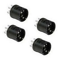
AL-C6V IDEC, AL-C6V Datasheet - Page 14

AL-C6V
Manufacturer Part Number
AL-C6V
Description
Adaptor Socket
Manufacturer
IDEC
Datasheet
1.LA9Z-S81B.pdf
(14 pages)
Specifications of AL-C6V
For Use With
A6 Series Switches And Pilot Devices
Lead Free Status / RoHS Status
Lead free / RoHS Compliant
470
Terminal Sockets
Dust Covers
AL-D6, Round
Pushbuttons with Standard Size Lens
Removal
Remove the lens holder assembly (lens, marking plate and holder) from the opera-
tor by holding the color lens recesses with the lens removal tool (Part No.MT-101)
and pulling out. Remove marking plate by pushing the color lens from the rear to
disengage the latches. Marking plate must be engraved on the side as shown in
the fi gure on the right.
Color Lens
Grooves
Ø 5/8” (16mm)
Style
Dimensions
Outside (OD)
Marking Area
(a)
Engraving
Surface
Engraving must be made on the engraving area within 0.02” (0.5mm) deep.
Fitting Grooves
Waterproof Gasket
for Dust Cover
Marking Plate
33.5
Round—AL6M-W
(13.8mm)
(12mm)
16.2
Solder Terminal Type
ø24
Marking
16mm A6
Area
Lens Holder
øa
7.5
( AL-C6 )
2.5
Square—AL6Q-W Rectangular—AL6H-W
(13.8mm)
(12mm)
6
TOP
Engraving
Ø 5/8” (16mm)
6
AL-DQ6, Square
Area
c
Waterproof Gasket
for Dust Cover
a
c
3
24
(OD
19.8mm
(a
1
xa
1
PC Board Terminal Type
x OD
2
) 12 x 18mm
Replacing & and Marking Plate
Engraving
Area
OD
a
2
) 13.8 x
2
2
( AL-C6V )
AL-DH6, Rectangular
33.5
Terminal 1.5×0.3t
www.idec.com
Marking Plates
16.2
Waterproof Gasket
for Dust Cover
30
Pushbuttons with Oversize Lens
Installation
For illuminated pushbuttons:
1. Insert marking plate inside lens in correct direction
2. Press color lens on to lens holder to engage latches.
3. Insert lens holder into housing in correct direction.
3.8
Style
Dimensions
Outside (OD)
Marking Area
(a)
Mounting Hole Layout
Do not loosen spring on illuminated pushbutton units (except on pilot light units). The
marking plate must be engraved on the front side as shown above.
(Bottom View)
2.5
PC Board
8-1.6
6
Round—AL6M-MW
øa
Ø 0.491” (12.6mm)
Ø 0.429” (11mm)
Panel Cut-Outs For Units w/Dust Cover
Round/Square
+0.3
6
0
Holes
3
ø16.2
+0.2
0
øOD
Lamp
Terminal (+)
24 min.
Marking
Area
Switches & Pilot Devices
Terminal Arrangement
(Bottom View)
NC1 NC2
NO1 NO2
( TOP )
C1
Square/Rectangular—AL6Q-QW
0.491” (12.6mm)
0.429” (11mm)
❏ OD
Rectangular
C2
Lamp
Terminal ( – )
ø16.2
+0.2
0
30 min.
❏a
Marking
Area


