RJ1P23I50E CARLO GAVAZZI, RJ1P23I50E Datasheet
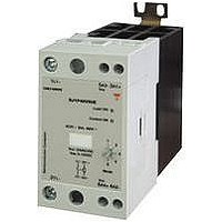
SSR, DIN RAIL MOUNT, 265VAC, 50A

RJ1P23I50E

Manufacturer Part Number
RJ1P23I50E
Description
SSR, DIN RAIL MOUNT, 265VAC, 50A
Manufacturer
CARLO GAVAZZI
Datasheet

Specifications of RJ1P23I50E

Operating Voltage Range
90VAC To 265VAC
Peak Surge Current
1.9kA
Contact Configuration
SPST
Load Current
50A
Switching Mode
Analog
Relay Terminals
Cage Clamp
Output Voltage Min
90V
Input Current Max
20mA
Specifications are subject to change without notice (05.10.2007)
Selection Guide
Rated operational
voltage
230VACrms
480VACrms
600VACrms
Note: Alarm Output: EPNO (NPN, normally open) and 600V types available only on request
Solid State Relays
SOLITRON MIDI Multi-Function Analog Switching
Type RJ1P
Product Description
The Solitron Midi Analog
Switching is a single-phase
SSR that provides proportional
output power in relation to the
control signal level applied.
This
device provides for 5 different
switching modes integrated
into one package. A selector
switch on the front of the
device is used for the selection
of the preferred mode of oper-
ation, i.e., either Phase Angle,
Distributed Full Cycle or Burst
Type Selection
Switching
mode
P: Proportional
*
*
1
2
PNP , Normally Open
NPN, Normally Open
Output
microprocessor-based
Rated operational
voltage
23: 230VACrms
48: 480VACrms
60: 600VACrms
Blocking
voltage
650Vp
1200Vp
1200Vp
Control. This multi-function
selection makes this device
ideal for the control of a variety
of loads, including heaters and
lamps. The control signal can
be either 4 - 20mA or 0 -
10VDC. 4mA or 0V correspond
to zero output power, whilst
20mA or 10VDC correspond to
full output power.
The product is ready to mount
on DIN-rail or chassis and
comes with integral heatsink.
Control
input
0-10VDC
4-20mA
0-10VDC
4-20mA
0-10VDC
4-20mA
Control
input
V: 0 - 10VDC
I: 4 - 20mA
Supply
voltage
24VAC/DC
24VAC/DC
24VAC/DC
Rated operational
current
30: 30AACrms
50: 50AACrms
• AC semiconductor contactor
• Multi-function - 5 selectable modes of operation: Phase
• Direct copper bonding (DCB) technology
• LED-indication for control and load status
• Operational ratings up to 50 AACrms and 600 VAC
• 4-20mA or 0-10V control input
• Built-in varistor
• Blocking voltage: Up to 1200Vp
• Opto-isolation > 4000VACrms
• Cage clamp terminals
• IP20 protection
• Option for over-temperature protection with alarm output
Ordering Key
Solid State Relay
Number of poles
Switching mode (Proportional)
Rated operational voltage
Control input type
Rated operational current
Terminal layout
Over-temperature protection
Alarm output type
Angle, Distributed Full Cycle and Burst Control (1, 3 and 10s)
Alarm
output type
PO
PO
-
PO
-
PO
-
-
-
-
Terminal
layout
E: Contactor
Rated operational current
30 A
RJ1P23V30E
RJ1P23V30EPPO
RJ1P23I30E
RJ1P23I30EPPO
RJ1P48V30E
RJ1P48V30EPPO
RJ1P48I30E
RJ1P48I30EPPO
RJ1P60V30E
RJ1P60I30E
RJ 1 P 48 V 50 E P PO
Protection
P: Over-
temperature NO: *
protection
50 A
RJ1P23V50E
RJ1P23V50EPPO
RJ1P23I50E
RJ1P23I50EPPO
RJ1P48V50E
RJ1P48V50EPPO
RJ1P48I50E
RJ1P48I50EPPO
RJ1P60V50E
RJ1P60I50E
Alarm
output type
PO: *
1
2
1

Related parts for RJ1P23I50E

RJ1P23I50E Summary of contents

Page 1

... PO 4-20mA - PO 0-10VDC 24VAC/ 4-20mA - PO 0-10VDC 24VAC/DC - 4-20mA - Terminal Protection Alarm layout output type E: Contactor P: Over- PO: * temperature NO: * protection Rated operational current RJ1P23V30E RJ1P23V50E RJ1P23V30EPPO RJ1P23V50EPPO RJ1P23I30E RJ1P23I50E RJ1P23I30EPPO RJ1P23I50EPPO RJ1P48V30E RJ1P48V50E RJ1P48V30EPPO RJ1P48V50EPPO RJ1P48I30E RJ1P48I50E RJ1P48I30EPPO RJ1P48I50EPPO RJ1P60V30E RJ1P60V50E RJ1P60I30E RJ1P60I50E ...

Page 2

RJ1P General Specifications Operational voltage range Blocking voltage Operational frequency range Output power Power factor Load status indication Output power resolution MODE 1 Phase Angle MODE 2 Full Cycle MODE 3 Burst with 1s period MODE 4 Burst with 3s ...

Page 3

RJ1P Connection Examples 1L1 ~ ~ LOAD 2T1 3A1 - 5A3: Control input current Example: RJ1P48I..E 1L1 ~ ~ LOAD 2T1 24VDC/AC 3A1 - 5A3 : Control Input Current Ic (4-20mA) 6A4 : Supply Voltage Vss (24VDC) 4A2 : Alarm ...

Page 4

RJ1P Operation MODE 1: The Phase Angle MODE The Burst switching mode works in Switching mode generates a accordance with the phase number of full cycles, depend- angle control principle, i.e. the ing on the control input ...

Page 5

RJ1P Functional Diagram Alarm Output Supply Control input MODE 1 Phase Angle MODE 2 Distributed Full Cycle MODE Burst 1s, 3s, 10s Dimensions Specifications are subject to change without notice (05.10.2007 (+) A3 (-) IC ...

Page 6

RJ1P Derating vs. Spacing Curves Note: Based on 100% output power 6 Surrounding temp. (˚C) Surrounding temp. (˚C) Specifications are subject to change without notice (05.10.2007) 22.5mm/ 10.0mm 6.0mm 3.0mm 0.0mm RJ1P...30 22.5mm/ 10.0mm 6.0mm 3.0mm 0.0mm RJ1P...50 ...

Page 7

RJ1P Derating vs. Spacing Curves (cont Specifications are subject to change without notice (05.10.2007 Surrounding temp. ...

Page 8

RJ1P Functional Diagram Mains Supply 24V Supply Control Input Green LED Red LED Output Alarm PNP* Alarm NPN* Over Temperature Sensing * Mains Supply 24V Supply * Control Input Green LED Red LED Output Alarm PNP* Alarm NPN* Over Temperature ...

Related keywords