PUB02CT23 CARLO GAVAZZI, PUB02CT23 Datasheet - Page 2
PUB02CT23
Manufacturer Part Number
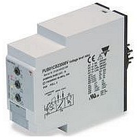
PUB02CT23
Description
VOLTAGE MONITORING RELAY, SPDT, 230VAC
Manufacturer
CARLO GAVAZZI
Series
PUB02r
Datasheet
1.PUB02CT23.pdf
(4 pages)
Specifications of PUB02CT23
Contact Configuration
SPDT
Power Consumption
4VA
Supply Voltage Max
230VAC
Relay Mounting
Plug In
Control Voltage Type
AC
Relay Terminals
Screw
Control Voltage
250V
Carry Current
8A


DUB02, PUB02
Supply Specifications
Power supply
Dielectric voltage
Supply to output
Rated operational power
General Specifications
Mode of Operation
DUB02 and PUB02 monitor
the TRMS value of their own
power supply.
Example 1
(no connection between ter-
minals Z1, Z2 or 8, 9 - Delay
ON alarm - N.E. relay)
The relay operates and the
yellow LED is ON as long as
the measured value is within
the upper and lower limits.
Function/Range/Level and Time Delay Setting
Adjust the input range setting
the DIP switches 5 and 6 as
shown on the right.
Select the desired function set-
ting the DIP switches 1 to 4 as
shown on the right.
To access the DIP switches
open the grey plastic cover as
shown on the right.
2
Power ON delay
Reaction time
Rated operational voltage
through terminals:
Dielectric voltage
Alarm ON delay
Alarm OFF delay
A1 and A2 (DUB02) or
2 and 10 (PUB02)
The relay releases after the
adjustable time delay when
the measured voltage exceeds
the upper set level or drops
below the lower set level.
The red LED flashes until the
delay time has expired or the
measured value falls off the
limits.
Example 2
(connection between termi-
Selection of level and time
delay:
Upper knob:
Setting of upper level on rela-
tive scale: -5% to +20% of
set power supply voltage.
Centre knob:
Setting of lower level on rela-
tive scale: -20% to +5% of
set power supply voltage.
Lower knob:
Setting of delay on alarm time
on absolute scale (0.1 to 30 s).
Overvoltage cat. III
(IEC 60664, IEC 60038)
24 VAC ± 20%,
115 VAC ± 20% or
230 VAC ± 20%
None
4 kV
4 VA
1 s ± 0.5 s or 6 s ± 0.5 s
(input signal variation from
-20% to +20% or from
+20% to -20% of set value)
< 200 ms
< 200 ms
General Specifications (cont.)
nals Z1, Z2 or 8, 9 - latching
function enabled - delay on
recovery - N.E. relay)
The relay operates and the
yellow LED is ON as long as
the measured value is within
the upper and lower limits.
The relay releases and latches
in alarm position as soon as
the measured voltage exceeds
the upper set level or drops
below the lower set level. Pro-
Accuracy
Indication for
Environment
Housing dimensions
Weight
Screw terminals
Approvals
CE Marking
EMC
Temperature drift
Delay ON alarm
Repeatability
Power supply ON
Alarm ON
Output relay ON
Degree of protection
Pollution degree
Operating temperature
Storage temperature
DIN-rail version
Plug-in version
Tightening torque
Immunity
Emission
Specifications are subject to change without notice (27.01.04)
Delay function
ON: Delay on recovery
OFF: Delay on alarm
Relay working mode
ON: Normally De-Energized
OFF: Normally Energized
Power ON delay
ON: 6 s ± 0.5 s
OFF: 1 s ± 0.5 s
Contact input
ON: Lacth function enable
OFF: Inhibit function enable
Measuring range
OFF OFF: 24 VAC
OFF ON:
ON OFF: 230 VAC
vided that the voltage has
dropped below the upper set
level (minus hysteresis) or
exceeded the lower set level
(plus hysteresis) for more than
the set delay time, the relay
operates when the intercon-
nections between terminals Z1,
Z2 or 8, 9 are interrupted. The
red LED flashes until the delay
time has expired or the mea-
sured value falls off the limits.
(15 min warm-up time)
± 1000 ppm/°C
± 10% on set value ± 50 ms
± 0.5% on full-scale
LED, green
LED, red (flashing 2 Hz
during delay time)
LED, yellow
IP 20
3 (DUB02), 2 (PUB02)
-20 to 60°C, R.H. < 95%
-30 to 80°C, R.H. < 95%
22.5 x 80 x 99.5 mm
36 x 80 x 87 mm
Approx. 150 g
Max. 0.5 Nm
acc. to IEC 60947
UL, CSA
Yes
Electromagnetic Compatibillity
According to EN 61000-6-2
According to EN 50081-1
115 VAC
Related parts for PUB02CT23
Image
Part Number
Description
Manufacturer
Datasheet
Request
R

Part Number:
Description:
MAGNETIC CYLINDRICAL PROX. SENSOR
Manufacturer:
CARLO GAVAZZI
Datasheet:
Part Number:
Description:
CYLINDRICAL MAGNETIC SENSOR
Manufacturer:
CARLO GAVAZZI
Datasheet:
Part Number:
Description:
MAGNETIC CYLINDRICAL PROX. SENSOR
Manufacturer:
CARLO GAVAZZI
Datasheet:
Part Number:
Description:
Current and Voltage Controls / Current Transformer / 3-Phase
Manufacturer:
Carlo Gavazzi
Datasheet:

Part Number:
Description:
Definite Purpose Contactor
Manufacturer:
CARLO GAVAZZI
Datasheet:
Part Number:
Description:
Definite Purpose Contactor
Manufacturer:
CARLO GAVAZZI
Datasheet: