LM317AT National Semiconductor, LM317AT Datasheet - Page 5
LM317AT
Manufacturer Part Number
LM317AT
Description
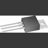
IC, ADJ LINEAR REG, 1.2V TO 37V, TO-220
Manufacturer
National Semiconductor
Datasheet
1.LM317AEMP.pdf
(28 pages)
Specifications of LM317AT
Primary Input Voltage
40V
Output Voltage Adjustable Range
1.2V To 37V
Dropout Voltage Vdo
2V
No. Of Outputs
1
No. Of Pins
3
Output Current
1.5A
Lead Free Status / RoHS Status
Contains lead / RoHS non-compliant
Available stocks
Company
Part Number
Manufacturer
Quantity
Price

Part Number:
LM317AT
Manufacturer:
NS/国半
Quantity:
20 000
Part Number:
LM317AT/NOPB
Manufacturer:
TI/德州仪器
Quantity:
20 000
Part Number:
LM317ATP+
Manufacturer:
NS/国半
Quantity:
20 000


Reference Voltage
Line Regulation
Load Regulation
Thermal Regulation
Adjustment Pin Current
Adjustment Pin Current Change
Temperature Stability
Minimum Load Current
Current Limit
RMS Output Noise, % of V
Ripple Rejection Ratio
Long-Term Stability
Thermal Resistance, θ
Junction-to-Case
Thermal Resistance, θ
Junction-to-Ambient
(No Heat Sink)
LM317A and LM317 Electrical Characteristics
Specifications with standard type face are for T
Range. Unless otherwise specified, V
Note 1: Absolute Maximum Ratings indicate limits beyond which damage to the device may occur. Operating Ratings indicate conditions for which the device is
intended to be functional, but do not guarantee specific performance limits. For guaranteed specifications and test conditions, see the Electrical Characteristics.
The guaranteed specifications apply only for the test conditions listed.
Note 2: Refer to RETS117H drawing for the LM117H, or the RETS117K for the LM117K military specifications.
Note 3: I
(TO-252), and E (LCC) packages. Device power dissipation (P
thermal resistance (θ
to National's Average Outgoing Quality Level (AOQL).
Note 4: Regulation is measured at a constant junction temperature, using pulse testing with a low duty cycle. Changes in output voltage due to heating effects
are covered under the specifications for thermal regulation.
Note 5: Human body model, 100 pF discharged through a 1.5 kΩ resistor.
Note 6: When surface mount packages are used (TO-263, SOT-223, TO-252), the junction to ambient thermal resistance can be reduced by increasing the PC
board copper area that is thermally connected to the package. See the Applications Hints section for heatsink techniques.
MAX
Parameter
= 1.5A for the K (TO-3), T (TO-220), and S (TO-263) packages. I
JA
). The maximum allowable power dissipation at any temperature is : P
JC
JA
OUT
3V
10 mA
3V
10 mA
20 ms Pulse
10 mA
3V
T
(V
(V
(V
10 Hz
V
V
T
K (TO-3) Package
T (TO-220) Package
S (TO-263) Package
EMP (SOT-223) Package
H (TO-39) Package
MDT (TO-252) Package
K (TO-3) Package
T (TO-220) Package
S (TO-263) Package
EMP (SOT-223) Package
H (TO-39) Package
MDT (TO-252) Package
MIN
J
OUT
OUT
IN
IN
K, S Packages
EMP, T Packages
H, MDT Packages
IN
K, S Packages
EMP, T Packages
H, MDT Packages
= 125°C, 1000 hrs
IN
≤
≤
≤
− V
− V
− V
≤
− V
(V
(V
(V
= 10V, f = 120 Hz, C
= 10V, f = 120 Hz, C
≤
≤
≤
≤
T
IN
IN
IN
OUT
OUT
OUT
J
OUT
f
I
I
I
OUT
OUT
OUT
≤
− V
− V
− V
≤
) = 40V
)
) = 40V
10 kHz
J
T
= 5V, and I
≤
OUT
OUT
OUT
MAX
= 25°C, and those with boldface type apply over full Operating Temperature
Conditions
≤
≤
≤
15V
D
) is limited by ambient temperature (T
I
I
I
)
MAX
)
MAX
MAX
)
≤
≤
≤
40V,
40V
40V
(Note
(Note
(Note
(Note
OUT
(Note
(Note
ADJ
ADJ
(Note
3)
3,
3)
6)
= 10 mA.
MAX
5
Note
= 0 μF
= 10 μF
6)
4)
= 1.0A for the EMP (SOT-223) package. I
6)
4)
D(MAX)
1.238
1.225
0.112
0.075
Min
1.5
0.5
66
(Note
-
-
= ((T
A
), device maximum junction temperature (T
LM317A
3)
J(MAX)
1.250
1.250
0.005
0.003
0.01
0.04
0.30
0.20
23.5
Typ
140
186
103
0.1
0.3
0.2
3.5
2.2
0.8
0.3
50
65
80
21
12
50
1
4
-
-
-
-
-
-
- T
A
)/θ
1.262
1.270
Max
0.01
0.02
0.07
100
0.5
3.4
1.8
JA
10
1
5
1
-
). All Min. and Max. limits are guaranteed
MAX
0.112
0.075
1.20
0.15
Min
1.5
1.5
0.5
66
-
= 0.5A for the H (TO-39), MDT
LM317
0.003
1.25
1.25
0.01
0.02
0.04
0.40
0.30
0.20
23.5
Typ
140
186
103
0.1
0.3
0.2
3.5
2.2
2.2
0.8
0.3
50
65
80
21
12
39
50
50
1
2
4
4
J
), and package
www.national.com
Max
1.30
0.04
0.07
0.07
100
0.5
1.5
3.4
3.4
1.8
10
5
1
-
Units
°C/W
°C/W
%/W
%/V
mA
μA
μA
dB
dB
%
%
%
%
V
V
A
A
Related parts for LM317AT
Image
Part Number
Description
Manufacturer
Datasheet
Request
R

Part Number:
Description:
Manufacturer:
National Semiconductor
Datasheet:
Part Number:
Description:
National Semiconductor [8-Bit D/A Converter]
Manufacturer:
National Semiconductor
Datasheet:
Part Number:
Description:
National Semiconductor [Media Coprocessor]
Manufacturer:
National Semiconductor
Datasheet:
Part Number:
Description:
Digitally Controlled Tone and Volume Circuit with Stereo Audio Power Amplifier, Microphone Preamp Stage and National 3D Sound
Manufacturer:
National Semiconductor
Datasheet:
Part Number:
Description:
Digitally Controlled Tone and Volume Circuit with Stereo Audio Power Amplifier, Microphone Preamp Stage and National 3D Sound
Manufacturer:
National Semiconductor
Datasheet:
Part Number:
Description:
AC97 Rev 2 Codec with Sample Rate Conversion and National 3D Sound
Manufacturer:
National Semiconductor
Part Number:
Description:
Manufacturer:
National Semiconductor
Datasheet:
Part Number:
Description:
Manufacturer:
National Semiconductor
Datasheet:
Part Number:
Description:
General Purpose, Low Voltage, Low Power, Rail-to-Rail Output Operational Amplifiers
Manufacturer:
National Semiconductor
Datasheet:
Part Number:
Description:
8-bit 20 MSPS flash A/D converter.
Manufacturer:
National Semiconductor
Datasheet:
Part Number:
Description:
Low Noise Quad Operational Amplifier
Manufacturer:
National Semiconductor
Datasheet:
Part Number:
Description:
Quad Differential Line Receivers
Manufacturer:
National Semiconductor
Datasheet:
Part Number:
Description:
Quad High Speed Trapezoidal? Bus Transceiver
Manufacturer:
National Semiconductor
Datasheet:
Part Number:
Description:
Dual Line Receiver
Manufacturer:
National Semiconductor
Datasheet: