SMD Inductors(Coils)
For Power Line(Wound, Magnetic Shielded)
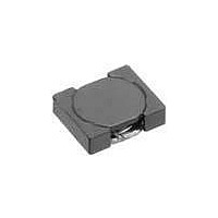
VLF-MT Series VLF302512MT
With the VLF302512MT Series, a DC to DC converter with top-
class voltage conversion efficiency for similar size products was
achieved by optimizing the magnetic material and configuration.
These products are optimal for use as choke coils in switching
power supplies such as those in mobile devices requiring space-
saving design.
FEATURES
• Miniature size
• Generic use for portable DC to DC converter line.
• High magnetic shield construction should actualize high resolu-
• The products contain no lead and also support lead-free
• The products is halogen-free.
• It is a product conforming to RoHS directive.
APPLICATIONS
Smartphones, cellular phones, DSCs, DVCs, HDDs, LCD displays,
compact power supply modules, etc.
SHAPES AND DIMENSIONS
RECOMMENDED PC BOARD PATTERN
CIRCUIT DIAGRAM
• Conformity to RoHS Directive: This means that, in conformity with EU Directive 2002/95/EC, lead, cadmium, mercury, hexavalent chromium, and specific
• Please contact our Sales office when your application are considered the following:
• All specifications are subject to change without notice.
0.9
The device’s failure or malfunction may directly endanger human life (e.g. application for automobile/aircraft/medical/nuclear power devices, etc.)
bromine-based flame retardants, PBB and PBDE, have not been used, except for exempted applications.
Mount area: 3.0×2.5mm
Low profile: 1.2mm max. height
tion for EMC protection.
soldering.
2.5±0.2
0.8
0.9
Dimensions in mm
( 0.7 )
( 0.8 )
( 0.7 )
Dimensions in mm
Weight: 0.033g
PRODUCT IDENTIFICATION
(1) Series name
(2) Dimensions L×W×H mm max.
(3) Packaging style
(4) Inductance value
(5) Inductance tolerance
PACKAGING STYLE AND QUANTITIES
Packaging style
Taping
HANDLING AND PRECAUTIONS
• Before soldering, be sure to preheat components.
• When hand soldering, apply the soldering iron to the printed
RECOMMENDED SOLDERING CONDITION
REFLOW SOLDERING
VLF 302512M
(1)
250 to 260˚C
230˚C
180˚C
150˚C
The preheating temperature should be set so that the
temperature difference between the solder temperature and
product temperature does not exceed 150°C.
circuit board only. Temperature of the iron tip should not exceed
350°C. Soldering time should not exceed 3 seconds.
T
1R0
100
M
N
(2)
Preheating
60 to 120s
(3)
T - 1R0 N
Time(s)
(4) (5)
002-02 / 20101028 / e531_vlf302512mt.fm
Soldering
30 to 60s
10s max.
Taping
(Embossed carrier tape)
1.0µH
10µH
±20%
±30%
Quantity
2000 pieces/reel
Conformity to RoHS Directive
Natural
cooling
(1/3)