MICRF505DEV1 Micrel Inc, MICRF505DEV1 Datasheet - Page 10
MICRF505DEV1
Manufacturer Part Number
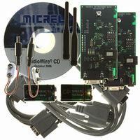
MICRF505DEV1
Description
KIT DEV RADIOWIRE 850-950MHZ
Manufacturer
Micrel Inc
Series
RadioWire®r
Type
Transceiver, ISMr
Specifications of MICRF505DEV1
Frequency
850MHz ~ 950MHz
For Use With/related Products
MICRF505
Lead Free Status / RoHS Status
Lead free / RoHS Compliant
Other names
576-1606
Available stocks
Company
Part Number
Manufacturer
Quantity
Price
Company:

Part Number:
MICRF505DEV1
Manufacturer:
Micrel Inc
Quantity:
135


MICRFXXX: User Manual for Development System, FW v.4
Combination #2, Transmit 1010… :
The board will enter transmit mode and transmit a 1010… pattern. This can be combined with
Combination #1 (Receive mode) to test range and error rate. Combination #2 can be used to
test parameters like deviation and transmit spectrum.
Combination #3, Transmit carrier:
The board will enter transmit mode and transmit a carrier, that is: no modulation is applied.
This can be used to check the frequency spectrum, the output power, and the current
consumption.
Combination #4, Enable configuration via PC:
This setting is also referred to as “PC mode”.
Refer to the chapter called “PC-Program” for details on the PC program.
Make sure the 4 jumpers “DTE_RTS”, “DTE_CTS”, “DTE_RX” and “DTE_TX” are in
place.
If the power-LEDs are off: Make sure the board is powered-on without the RS232 cable
connected, and then connect the cable.
Entering “PC mode”: Before any command is given from the PC, the RF chip will stay in
receive or transmit mode, depending on the selected mode before entering “PC mode”.
While in “PC mode”: When a control word is sent from the PC to the board, the board will
store the entered word in EEPROM and program the RF chip with it.
It is possible to transfer a control word from 2 dialog boxes (press the “Transfer” button
inside the dialog box):
Main menu
Main menu
When leaving “PC mode”: The board will use the default control word already programmed
into the flash program memory, or it will use the control word entered from the PC program
and stored in the EEPROM. Which one to select (the source of the control word) is selected in
the PC program (select RF TestBench
From the PC program, try e.g. to change the output power level (PA setting) and observe the
effect on spectrum, power consumption and link range.
Combination #5, Bypass Micro Controller:
Using this combination, it is possible to use an external micro controller to control the RF
part. Connect to the interface pins as described in “Development Board Inputs/Outputs”.
1
Transfer Mode”. It will not be used in “Advanced Byte Transfer Mode”. If the “EEPROM control word” is used
in “2-Way Link Test Mode”: No frequency jumping is done – only the control word stored in EEPROM will be
used.
Micrel Norway, Oslo Norway
The “EEPROM control word” can be used in “RF Test Modes”, “2-way Link Test Mode” and “Simple Byte
RF TestBench
RF TestBench
Quick Setup or
Complete Setup
Development Board Commands)
1
.
9
Related parts for MICRF505DEV1
Image
Part Number
Description
Manufacturer
Datasheet
Request
R

Part Number:
Description:
Manufacturer:
Micrel Inc
Datasheet:
Part Number:
Description:
Manufacturer:
Micrel Inc
Datasheet:
Part Number:
Description:
Manufacturer:
Micrel Inc
Datasheet:
Part Number:
Description:
Manufacturer:
Micrel Inc
Datasheet:
Part Number:
Description:
Manufacturer:
Micrel Inc
Datasheet:
Part Number:
Description:
Manufacturer:
Micrel Inc
Datasheet:
Part Number:
Description:
Manufacturer:
Micrel Inc
Datasheet:
Part Number:
Description:
Manufacturer:
Micrel Inc
Datasheet:
Part Number:
Description:
Manufacturer:
Micrel Inc
Datasheet:
Part Number:
Description:
Manufacturer:
Micrel Inc
Datasheet:
Part Number:
Description:
Manufacturer:
Micrel Inc
Datasheet:
Part Number:
Description:
Manufacturer:
Micrel Inc
Datasheet:
Part Number:
Description:
Manufacturer:
Micrel Inc
Datasheet:
Part Number:
Description:
Manufacturer:
Micrel Inc
Datasheet: