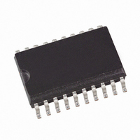
U2794B-NFSH Atmel, U2794B-NFSH Datasheet

U2794B-NFSH
Specifications of U2794B-NFSH
Related parts for U2794B-NFSH
U2794B-NFSH Summary of contents
Page 1
... Easy to Implement • Perfect Performance for Large Variety of Wireless Applications 1. Description The silicon monolithic integrated circuit U2794B is a quadrature demodulator manu- ® factured using Atmel ’s advanced UHF technology. This demodulator features a frequency range from 70 MHz to 1000 MHz, low current consumption, selectable gain, power-down mode, and adjustment-free handling ...
Page 2
... RFX RFX input lowpass filter Q 10 QQX QQX lowpass filter gain control 12 PCX PCX phase control phase control power up 15 LOX LOX input in 16 GND Ground input in 18 GND Ground output output U2794B GND 17 4 IIX GND LOX RFX PCX ...
Page 3
... Thermal Resistance Parameters Junction ambient SSO20 5. Operating Range Parameters Supply-voltage range Ambient-temperature range 4653F–CELL–11/08 Symbol Value +125 j T –55 to +125 stg Symbol Value R 140 thJA Symbol Value V 4. –40 to +85 amb U2794B Unit °C °C Unit K/W Unit V °C 3 ...
Page 4
... For low signal distortion the load impedance should Referred to the level of the output vector 8. The low-gain status is achieved with an open or high-ohmic pin 11. A recommended application circuit for switching between high and low gain status is shown in U2794B 25°C, referred to test circuit ...
Page 5
... Figure 6- < open Figure 6-1. Min. Typ. Max. BWI –0.5 ±0.2 +0.5 Pe –3 ±1 2.5 2.8 3.1 OUT V < 5 offset Z 50 out GCR – < 4 SON T < 4 SOFF Figure 6-6 U2794B Unit Type* MHz Deg Test mV spec µs D µs D (VS –0.8V)/RI 5 ...
Page 6
... Figure 6-1. * optional for single-ended tests (notice 3 dB bandwidth of AD620) T1 transmission line function is required, connect Pin 11 to GND. For high and low gain status GC´ switched to GND respectively to V Figure 6-2. U2794B 6 Test Circuit = and Q phase for f > For 1.5 1 ...
Page 7
... Typical VSWR Frequency Response of the LO Input 250 450 LO Frequency ( MHz ) Noise Figure versus LO Frequency; o: Value at 950 MHz with RF Input Matching with 200 400 LO Frequency (MHz) Typical Suitable LO Power Range versus Frequency 0 -10 -20 -30 -40 - Frequency (MHz) U2794B 1050 650 850 600 800 1000 P LOmax P LOmin ...
Page 8
... Figure 6-6. Figure 6-7. Figure 6-8. U2794B 8 Gain versus LO Frequency; x: Value at 950 MHz with RF Input Matching with 200 400 LO Frequency (MHz) Typical Output Signal versus LO Frequency for P PLO = 15 dBm – 1600 1500 1400 1300 1200 1100 1000 900 800 0 200 400 ...
Page 9
... I/Q Outputs, Baseband Frequency from 5 MHz to 55 MHz, marker: 25 MHz 4653F–CELL–11/08 Typical Output Voltage (Single Ended) versus P PLO = 15 dBm – 1800 1600 1400 1200 1000 800 600 400 200 0 -40 -35 - 0.5j 0. 0.2 0.5 -0.2j -0.5j -j U2794B 25°C and RF amb -25 -20 -15 -10 (dBm -5j -2j 9 ...
Page 10
... Figure 6-11. Evaluation Board Layout Figure 6-12. Evaluation Board U2794B 10 4653F–CELL–11/08 ...
Page 11
... RF-input matching, to connect optionally optional for AC-coupling at baseband outputs 100 pF not connected 100 pF 100 pF not connected 100 pF not connected gain switch 100 pF 50 AD620 prog. gain, see datasheet, for 5.6 k achieved together with RD1 and RD2. 450 100 nF 100 nF U2794B a gain ...
Page 12
... Board material: epoxy 4.8, thickness = 0.5 mm, transmission lines: Z The board offers the following functions: • Test circuit for the U2794B: – The supply voltage and the control inputs GC, PC, and PU are connected via a plug – The outputs I, IX are DC coupled via an plug strip or can be AC-connected – ...
Page 13
... Ordering Information Extended Type Number U2794B-NFSH U2794B-NFSG3H 9. Package Information 0.25 ±0. Drawing-No.: 6.543-5056.01-4 Issue: 1; 10.03.04 4653F–CELL–11/08 Package SSO20 SSO20 6.75 -0.25 0.65 ±0.05 5.85 ±0. Remarks Tube, MOQ 830 pcs, Pb-free Taped and reeled, MOQ 4000 pcs, Pb-free 5.4 ± ...
Page 14
... Please note that the following page numbers referred to in this section refer to the specific revision mentioned, not to this document. Revision No. 4653F-CELL-11/08 4653E-CELL-07/06 U2794B 14 History Put datasheet in the newest template ESD logo on page 1 deleted Section 6 “Electrical Characteristics” number 7.1 on page 6 changed Put datasheet in the newest template Section 3 “ ...
Page 15
... Disclaimer: The information in this document is provided in connection with Atmel products. No license, express or implied, by estoppel or otherwise, to any intellectual property right is granted by this document or in connection with the sale of Atmel products. EXCEPT AS SET FORTH IN ATMEL’S TERMS AND CONDI- TIONS OF SALE LOCATED ON ATMEL’S WEB SITE, ATMEL ASSUMES NO LIABILITY WHATSOEVER AND DISCLAIMS ANY EXPRESS, IMPLIED OR STATUTORY WARRANTY RELATING TO ITS PRODUCTS INCLUDING, BUT NOT LIMITED TO, THE IMPLIED WARRANTY OF MERCHANTABILITY, FITNESS FOR A PARTICULAR PURPOSE, OR NON-INFRINGEMENT ...


