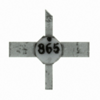
MGA-86576-STRG Avago Technologies US Inc., MGA-86576-STRG Datasheet

MGA-86576-STRG
Specifications of MGA-86576-STRG
516-2131-2
516-2131-2
Available stocks
Related parts for MGA-86576-STRG
MGA-86576-STRG Summary of contents
Page 1
... Surface Mount Ceramic Package Pin Connections MGA-86576 Pkg 4 GROUND RF OUTPUT RF INPUT AND GROUND 2 MGA-86576 Pin Connection Features • 1.6 dB Noise Figure at 4 GHz • Gain at 4 GHz • +6 dBm P • Single +5 V Bias Supply Applications • LNA or Gain Stage for 2.4 GHz and 5.7 GHz ISM Bands • Front End Amplifier for GPS Receivers • LNA or Gain Stage for PCN and MMDS Applications • C-Band Satellite Receivers • Broadband Amplifier for Instrumentation ...
Page 2
... Absolute Maximum Ratings Symbol Parameter V Device Voltage, RF output d to ground V Device Voltage, RF input g to ground Input Power in T Channel Temperature ch T Storage Temperature STG MGA-86576 Electrical Specifications, Symbol Parameters and Test Conditions Gp Power Gain (| NF 50 Ω Noise Figure 50 NF Optimum Noise Figure o (Input tuned for lowest noise figure) P Output Power Gain 1dB Compression IP Third Order Intercept Point 3 VSWR Input VSWR ...
Page 3
... Figure 1. Power Gain vs. Frequency at Three Tempera- tures. MGA-86576 fig 1 10.0 -40°C 8.0 +25°C 6.0 +50°C 4.0 2 FREQUENCY (GHz) Figure 4. P vs. Frequency at Three Temperatures. 1dB MGA-86576 fig 4 MGA-86576 Typical Scattering Parameters Freq GHz Mag Ang 0.5 0.57 -21 1.0 0.55 -30 1.5 0.54 -44 2.0 0.52 -59 2.5 0.48 -77 3 ...
Page 4
... Reference plane taken at point where leads meet body of package. MGA-86576 Applications Information Introduction The MGA-86576 is a high gain, broad band, low noise amplifier. The use of plated through holes or an equiva- lent minimal inductance grounding technique placed precisely under each ground lead at the device is highly recom-mended. A minimum of two plated through holes under each ground lead is preferred with four being highly suggested. A long ground path to pins 2 and 4 will add additional inductance which can cause gain peaking in the GHz frequency range ...
Page 5
... Volt Bias for Operation at Higher Temperatures The MGA-86576 was designed primarily for 5 volt op- eration over the -25 to +50°C temperature range. For applications requiring use to +85° volt bias supply is recommended to minimize changes in gain and noise figure at elevated temperature. Figure 10 shows typical gain, noise figure, and output power performance over temperature at 4 GHz with 7 volts applied. With a 7 volt bias supply, output power is increased approximately 1 ...
Page 6
... Part Number Devices MGA-86576-TR1 1000 MGA-86576-STRG 100 For product information and a complete list of distributors, please go to our web site: vago, Avago Technologies, and the A logo are trademarks of Avago Technologies Limited in the United States and other countries. Data subject to change. Copyright © 2005-2008 Avago Technologies Limited. All rights reserved. Obsoletes 5989-4658EN ...


