ATAVRRZ200 Atmel, ATAVRRZ200 Datasheet
ATAVRRZ200
Specifications of ATAVRRZ200


Related parts for ATAVRRZ200


ATAVRRZ200 Summary of contents
Page 1
... ATAVRRZ200 Demonstration Kit AT86RF230 (2450 MHz band) Radio Transceiver .............................................................................................. User Guide ...
Page 2
...
Page 3
... Starting the network ..................................................................................5-1 5.2 Reconfiguring the network ........................................................................5-3 5.3 Using the network .....................................................................................5-3 Section 6 6.1 Atmel AVR Studio installation ...................................................................6-1 6.2 Overview of the programming process .....................................................6-1 6.2.1 Programming the Display Board.........................................................6-2 6.2.2 Programming the RCB .......................................................................6-2 6.2.3 How to re-program the RCB MAC address ........................................6-3 ...
Page 4
Demonstration Kit User Guide ...
Page 5
... Self-healing functions can be added at the network/application layers to automatically replace a failed PAN coordinator. This demonstration kit shows how it is possible to change the role of a network device over the wireless link. Such functionality is benefi- cial in self-healing networks. ® ® ™ AVR Z-Link ATAVRRZ200 Demon- 5183A–ZIGB–12/07/06 1-1 ...
Page 6
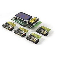
... Board) Simple application interface (pushbutton switches and LEDs) Wide application usage Choice of RCB application software How to use the Atmel IEEE 802.15.4 communication-stack Non-beacon-enabled network IEEE 802.15.4 compliant The kit features two component types: the Display Board and the Radio Controller Boards (RCBs) ...
Page 7
... On the Display Board, move the power switch toward the edge of the board (BAT). 2. When the Atmel splash screen is displayed, move the power switch on the attached RCB away from the antenna to the ON position. 3. Observe the LCD display indicate channel scan. 4. One at a time, sequentially turn on the four remaining RCBs. ...
Page 8
Randomly change the functionality of the RCBs in the Configure screen by first selecting the desired unit by pressing the joystick up or down, then press SW2 to change the function to either an LED unit or ...
Page 9
Z-Link RCBs 3.2 Display Board Demonstration Kit User Guide Section 3 Hardware Description This section contains a description of the hardware furnished with the Demonstration Kit. The five RCBs are identical and each contains a radio and microcontroller. The ...
Page 10
Figure 3-2. Key Components of the Display Board Figure 3-3. RCB Mounted on the Display Board Demonstration Kit User Guide ...
Page 11
Demonstration Kit User Guide Figure 3-4. Display Board connectors 3-3 5183A–ZIGB–12/07/06 ...
Page 12
Demonstration Kit User Guide ...
Page 13
Channel Scan Demonstration Kit User Guide Section 4 This section describes how the software furnished with the kit is used to demonstrate a simple IEEE 802.15.4 network operating with a star topology. The star network is shown below in ...
Page 14
End Device Association & Network Configuration 4.3 Network Operation 4-2 5183A–ZIGB–12/07/06 As each End Device is turned on, it performs an active scan of all channels from 11 to 26, broadcasting a Beacon Request and recording all information that ...
Page 15
... After the RCB is connected to the Display Board, the power switch on the Display Board should be moved to BAT for battery power, or EXT for AC Adaptor power. The Atmel splash screen is displayed on the LCD display similar to that shown in Figure 5-1. ...
Page 16
Figure 5-3. Channel selected and waiting for nodes. The four remaining RCBs can now be powered on in random order. Figure 5-4 through Figure 5-7 shows the Configure screen as the nodes are powered on. Figure 5-4. First ...
Page 17
Reconfiguring the network 5.3 Using the network Demonstration Kit User Guide All configurations of the network nodes are performed in the Configure screen on the Display Board. Note: This demonstration requires at least two nodes to associate with the ...
Page 18
Each RCB configured as an LED unit will show the state of the switch device’s value (on or off). The value of the LEDs will also be shown on the Display Board in the network monitor screen. The ...
Page 19
... The following paragraphs overview the installation and use of the Atmel AVRISP mkII In-system Programmer. The AVRISP and JTAGICE are other tools supplied by Atmel that can be used for pro- gramming the RCBs. If the STK500 ISP port is used, be sure to remove the VTARGET jumper. This should be done to prevent voltage conflicts between the STK500 platform and RCB ...
Page 20
Programming the Display Board 6.2.2 Programming the RCB 6-2 5183A–ZIGB–12/07/06 The following steps show how to re-program the ATmega128 microcontroller located on the Display Board. Remove RCB from Display board. 1. Connect the 6-pin cable from the AVRISP mkII ...
Page 21
How to re-program the RCB MAC address Demonstration Kit User Guide 5. Go back to the Program tab, in the Flash section, browse to the location of the input HEX file and select the filename: rz200_v1_0.hex. Press Program and ...
Page 22
Demonstration Kit User Guide ...
Page 23
Table 7-1. Troubleshooting Problem Reason No response from any board Power Switch is OFF Dead Batteries The LEDs on the Z-Link RCB The RCB is not configured as an will not illuminate LED Unit Power Switch is OFF Dead Batteries ...
Page 24
Demonstration Kit User Guide ...
Page 25
... Disclaimer: The information in this document is provided in connection with Atmel products. No license, express or implied, by estoppel or otherwise, to any intellectual property right is granted by this document or in connection with the sale of Atmel products. EXCEPT AS SET FORTH IN ATMEL’S TERMS AND CONDI- TIONS OF SALE LOCATED ON ATMEL’S WEB SITE, ATMEL ASSUMES NO LIABILITY WHATSOEVER AND DISCLAIMS ANY EXPRESS, IMPLIED OR STATUTORY WARRANTY RELATING TO ITS PRODUCTS INCLUDING, BUT NOT LIMITED TO, THE IMPLIED WARRANTY OF MERCHANTABILITY, FITNESS FOR A PARTICULAR PURPOSE, OR NON-INFRINGEMENT ...