M52277EVB Freescale Semiconductor, M52277EVB Datasheet - Page 20
M52277EVB
Manufacturer Part Number
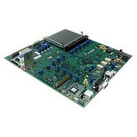
M52277EVB
Description
BOARD DEMO FOR MCF5227
Manufacturer
Freescale Semiconductor
Series
ColdFire®r
Type
MCUr
Specifications of M52277EVB
Contents
Board
Silicon Manufacturer
Freescale
Core Architecture
Coldfire
Core Sub-architecture
Coldfire V2
Silicon Core Number
MCF52
Silicon Family Name
MCF5227x
Peak Reflow Compatible (260 C)
Yes
Rohs Compliant
Yes
For Use With/related Products
MCF52277
Lead Free Status / RoHS Status
Lead free / RoHS Compliant


Electrical Characteristics
5.6
Table 12
20
ASP Analog Supply Voltage
Input Voltage Range
Operating Current Consumption
Power-down Current Consumption
Resolution
Sampling rate
Differential Non-linearity
ADC Internal Clock Frequency
Conversion Range
Integral Non-linearity
1
2
3
4
5
6
7
8
Num
Although these are the allowable frequency ranges, do not violate the VCO frequency range of the PLL. See the
MCF5227x Reference Manual for more details.
The minimum system frequency is the minimum input clock divided by the maximum low-power divider
(16 MHz ÷ 32,768). When the PLL is enabled, the minimum system frequency (f
This parameter is guaranteed by characterization before qualification rather than 100% tested. Applies to external clock
reference only.
Proper PC board layout procedures must be followed to achieve specifications.
This parameter is guaranteed by design rather than 100% tested.
This specification is the PLL lock time only and does not include oscillator start-up time..
C
Jitter is the average deviation from the programmed frequency measured over the specified interval at maximum f
Measurements are made with the device powered by filtered supplies and clocked by a stable external clock signal.
Noise injected into the PLL circuitry via PLL V
the Cjitter percentage for a given interval.
13
14
15
17
19
S_PCB
lists the electrical specifications for the ASP module.
ASP Electrical Characteristics
Discrete load capacitance for XTAL
Discrete load capacitance for EXTAL
Frequency un-LOCK Range
Frequency LOCK Range
CLKOUT period jitter
VCO frequency (f
is the measured PCB stray capacitance on EXTAL and XTAL.
Peak-to-peak jitter (Clock edge to clock edge)
Long-term jitter
Characteristic
vco
Table 11. PLL Electrical Characteristics (continued)
= f
MCF5227x ColdFire
Characteristic
4, 5, 8
ref
× PFDR)
measured at f
Table 12. ASP Electrical Characteristics
DD
sys
, EV
®
Microprocessor Data Sheet, Rev. 8
max
DD
, and V
I
Symbol
I
DDA_OFF
DDA_ON
V
V
DNL
R
R
INL
t
ADIN
AIC
DDA
AD
ES
SS
and variation in crystal oscillator frequency increase
C
Symbol
C
L_EXTAL
C
L_XTAL
f
f
f
LCK
vco
UL
jitter
Min
3.0
—
—
—
—
—
—
0
2
0
sys
) is 37.5 MHz.
–4.0
–2.0
Min
350
Typical
—
—
—
700
—
—
—
—
±8
±2
—
—
1
C
C
C
Freescale Semiconductor
2 × (C
S_EXTAL
S_XTAL
S_PCB
TBD
Max
540
4.0
2.0
10
V
V
Max
125
±24
±24
3.6
12
L
DDA
—
—
DDA
8
)
–
7
–
–
% f
% f
% f
% f
MHz
Unit
pF
sys/2
sys/2
sys
sys
Unit
kS/s
MHz
sys
lsb
lsb
bits
uA
uA
V
V
V
.
1
1
Related parts for M52277EVB
Image
Part Number
Description
Manufacturer
Datasheet
Request
R

Part Number:
Description:
Manufacturer:
Freescale Semiconductor, Inc
Datasheet:
Part Number:
Description:
Manufacturer:
Freescale Semiconductor, Inc
Datasheet:
Part Number:
Description:
Manufacturer:
Freescale Semiconductor, Inc
Datasheet:
Part Number:
Description:
Manufacturer:
Freescale Semiconductor, Inc
Datasheet:
Part Number:
Description:
Manufacturer:
Freescale Semiconductor, Inc
Datasheet:
Part Number:
Description:
Manufacturer:
Freescale Semiconductor, Inc
Datasheet:
Part Number:
Description:
Manufacturer:
Freescale Semiconductor, Inc
Datasheet:
Part Number:
Description:
Manufacturer:
Freescale Semiconductor, Inc
Datasheet:
Part Number:
Description:
Manufacturer:
Freescale Semiconductor, Inc
Datasheet:
Part Number:
Description:
Manufacturer:
Freescale Semiconductor, Inc
Datasheet:
Part Number:
Description:
Manufacturer:
Freescale Semiconductor, Inc
Datasheet:
Part Number:
Description:
Manufacturer:
Freescale Semiconductor, Inc
Datasheet:
Part Number:
Description:
Manufacturer:
Freescale Semiconductor, Inc
Datasheet:
Part Number:
Description:
Manufacturer:
Freescale Semiconductor, Inc
Datasheet:
Part Number:
Description:
Manufacturer:
Freescale Semiconductor, Inc
Datasheet: