M52277EVB Freescale Semiconductor, M52277EVB Datasheet - Page 17
M52277EVB
Manufacturer Part Number
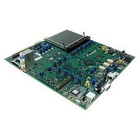
M52277EVB
Description
BOARD DEMO FOR MCF5227
Manufacturer
Freescale Semiconductor
Series
ColdFire®r
Type
MCUr
Specifications of M52277EVB
Contents
Board
Silicon Manufacturer
Freescale
Core Architecture
Coldfire
Core Sub-architecture
Coldfire V2
Silicon Core Number
MCF52
Silicon Family Name
MCF5227x
Peak Reflow Compatible (260 C)
Yes
Rohs Compliant
Yes
For Use With/related Products
MCF52277
Lead Free Status / RoHS Status
Lead free / RoHS Compliant


5.2
The average chip-junction temperature (T
Where:
For most applications P
Solving equations 1 and 2 for K gives:
where K is a constant pertaining to the particular part. K can be determined from
for a known T
for any value of T
Freescale Semiconductor
1
2
3
4
5
Junction to ambient, natural convection
Junction to ambient (@200 ft/min)
Junction to board
Junction to case
Junction to top of package
Maximum operating junction temperature
θ
Freescale recommends the use of θ
junction temperatures from exceeding the rated specification. System designers should be aware that device
junction temperatures can be significantly influenced by board layout and surrounding devices. Conformance to the
device junction temperature specification can be verified by physical measurement in the customer’s system using
the Ψ
Per JEDEC JESD51-6 with the board horizontal.
Thermal resistance between the die and the printed circuit board in conformance with JEDEC JESD51-8. Board
temperature is measured on the top surface of the board near the package.
Thermal resistance between the die and the case top surface as measured by the cold plate method (MIL
SPEC-883 Method 1012.1).
Thermal characterization parameter indicating the temperature difference between package top and the junction
temperature per JEDEC JESD51-2. When Greek letters are not available, the thermal characterization parameter
is written in conformance with Psi-JT.
T
Q
P
P
P
JA
A
JMA
D
INT
I/O
, θ
Thermal Characteristics
jt
JMA
A
parameter, the device power dissipation, and the method described in EIA/JESD Standard 51-2.
. Using this value of K, the values of P
and Ψ
A
.
= Ambient Temperature, °C
= Package Thermal Resistance, Junction-to-Ambient, °C/W
= P
= I
= Power Dissipation on Input and Output Pins — User Determined
I/O
INT
DD
jt
parameters are simulated in conformance with EIA/JESD Standard 51-2 for natural convection.
< P
× IV
+ P
INT
Characteristic
I/O
DD
MCF5227x ColdFire
and can be ignored. An approximate relationship between P
, Watts - Chip Internal Power
K
J
) in °C can be obtained from:
=
JmA
Table 8. Thermal Characteristics
P
and power dissipation specifications in the system design to prevent device
D
Four layer board (2s2p)
Four layer board (2s2p)
T
J
×
P
(
=
D
T
D
T
=
A
®
and T
A
×
-------------------------------- -
(
Microprocessor Data Sheet, Rev. 8
+
T
273°C
J
(
P
+
J
D
K
can be obtained by solving
273
×
)
Θ
°
+
JMA
C
Q
)
JMA
)
×
Symbol
P
θ
2
D
θ
θ
θ
Ψ
JMA
T
JA
JB
JC
jt
j
Equation 3
MAPBGA
Equation 1
38
34
196
4
105
27
17
by measuring P
1,5
1,2
1,2
3
4
D
and T
Electrical Characteristics
and
J
(if P
LQFP
Equation 2
48
42
176
3
105
37
14
1,5
1,2
1,2
I/O
3
4
D
(at equilibrium)
is neglected) is:
°C / W
°C / W
°C / W
°C / W
°C / W
Unit
iteratively
o
C
Eqn. 1
Eqn. 2
Eqn. 3
17
Related parts for M52277EVB
Image
Part Number
Description
Manufacturer
Datasheet
Request
R

Part Number:
Description:
Manufacturer:
Freescale Semiconductor, Inc
Datasheet:
Part Number:
Description:
Manufacturer:
Freescale Semiconductor, Inc
Datasheet:
Part Number:
Description:
Manufacturer:
Freescale Semiconductor, Inc
Datasheet:
Part Number:
Description:
Manufacturer:
Freescale Semiconductor, Inc
Datasheet:
Part Number:
Description:
Manufacturer:
Freescale Semiconductor, Inc
Datasheet:
Part Number:
Description:
Manufacturer:
Freescale Semiconductor, Inc
Datasheet:
Part Number:
Description:
Manufacturer:
Freescale Semiconductor, Inc
Datasheet:
Part Number:
Description:
Manufacturer:
Freescale Semiconductor, Inc
Datasheet:
Part Number:
Description:
Manufacturer:
Freescale Semiconductor, Inc
Datasheet:
Part Number:
Description:
Manufacturer:
Freescale Semiconductor, Inc
Datasheet:
Part Number:
Description:
Manufacturer:
Freescale Semiconductor, Inc
Datasheet:
Part Number:
Description:
Manufacturer:
Freescale Semiconductor, Inc
Datasheet:
Part Number:
Description:
Manufacturer:
Freescale Semiconductor, Inc
Datasheet:
Part Number:
Description:
Manufacturer:
Freescale Semiconductor, Inc
Datasheet:
Part Number:
Description:
Manufacturer:
Freescale Semiconductor, Inc
Datasheet: