M52277EVB Freescale Semiconductor, M52277EVB Datasheet
M52277EVB
Specifications of M52277EVB


Related parts for M52277EVB

M52277EVB Summary of contents
Page 1
... Applicable Documents • MCF52277 Reference Manual • Universal Serial Bus Specification, Revision 2.0 © Freescale Semiconductor, Inc., 2010. All rights reserved. M52277EVBUM Rev. 0.8, 03/2010 Contents 1 Introduction . . . . . . . . . . . . . . . . . . . . . . . . . . . . . . . . . . . 1 2 Applicable Documents . . . . . . . . . . . . . . . . . . . . . . . . . . . 1 3 Evaluation Board Overview . . . . . . . . . . . . . . . . . . . . . . . 2 3 ...
Page 2
... NOR Flash • 16Mbit Serial Boot Flash Power: • Inputs: — Input to the voltage regulator circuitry • Regulated On-board voltages: — 3 I/O Voltage — 1 Mobile DDR and Flash Voltage — 1 MCF52277 Core Voltage 2 M52277 Evaluation Board, Rev. 0.8 Freescale Semiconductor ...
Page 3
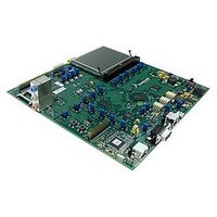
... Board Diagram Freescale Semiconductor Figure 1. Board Diagram M52277 Evaluation Board, Rev. 0.8 3 ...
Page 4
... GPIO, control structures or other I/Os. In Table 1, you'll find the details on how we've set up the first FlexBus region on the M52277EVB. We don't set up the second FlexBus memory region. Component Spansion S29WS128J0PBFW010 ...
Page 5
... MCF52277 processor reset negates, ensuring the chip is properly configured when exiting the reset state. 5.5 SDRAM Interface The M52277EVB provides 64 Mbytes of on-board Mobile SDRAM (16bit x 32M Micron Mobile SDRAM). On-board terminations are provided. Freescale Semiconductor Table 2. M52277EVB Clock Definitions ...
Page 6
... RS232 The MCF52277 includes 3 UART modules. The M52277EVB provides one standard RS232 line driver necessary to interface with RS232 connectors. The board also supplies a USB-to-UART bridge to interface with the MCF52277’s UART0. If using this option, a USB type B connector can be used to interface with an external device, instead of the standard RS232 connector ...
Page 7
... ON OFF SW3-1 (none) ON OFF Freescale Semiconductor Table 3. SW3, SW4, and SW5 Settings 1 Boot from SPI Flash and override RCON (Serial RCON) Boot from FlexBus with RCON defaults, split bus (16-Bit/16-Bit) Boot from FlexBus override RCON (Parallel RCON) Boot from FlexBus with RCON defaults, unified bus (32-Bits) ...
Page 8
... Bold indicates the default setting, SW5-3, SW5-4, and SW4-4 are not connected and their position does not affect configuration. 5.14 Jumpers, Headers, and Switches There are several jumpers on the M52277EVB that allow for user control of the hardware configuration. The following table provides descriptions for all the jumper settings. 1,2 Reference Designator Setting ...
Page 9
... Connects pin 3 of the DB-9 connector J29 to GND for CAN operation 1-2 Sets the PSTCLK/TCLK signal up as TCLK J19 Sets the PSTCLK/TCLK signal up as PSTCLK for BDM Debug (Default for this jumper is 2-3 “not installed”) Freescale Semiconductor Table 4. Jumper Settings (continued) Function M52277 Evaluation Board, Rev. 0.8 9 ...
Page 10
... Sets the clock input to be either from an external source board 16MHz Oscillator, depending on the setting of J21 Sets the clock input to be from an on board 16MHz crystal Connects the ADC_REF signal to ADC_VDD Connects the ADC_REF signal to ADC_VSS M52277 Evaluation Board, Rev. 0.8 Function Freescale Semiconductor ...
Page 11
... LogicPD LCD Connector J17 BDM Connector J24 SMA Connector for external clock source J25 USB B Connector - Used to communicate with the M52277EVB’s on board USB to BDM Debug Port J26 USB B Connector - Used to communicate with on board serial to USB converter connected to UART0 J27 Mini USB A/B Connector - Connected to the MCF52277’ ...
Page 12
... Reference Designator 12 Table 7. Test Points Signal TP1 VSS TP2 VSS TP3 RSTOUT_B TP4 RESET_B TP5 SD_SDR_DQS TP6 CS0_B TP7 USB_VBUS_EN TP8 FLASH RDY TP9 RW_B TP10 VSS TP11 V1.2 TP12 CAN VREF TP13 VSS M52277 Evaluation Board, Rev. 0.8 Freescale Semiconductor ...