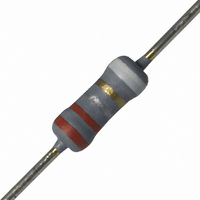
NFR25H0002207JR500 Vishay, NFR25H0002207JR500 Datasheet - Page 7

NFR25H0002207JR500
Manufacturer Part Number
NFR25H0002207JR500
Description
RES .22 OHM .50W 5% MF FUSIBLE
Manufacturer
Vishay
Series
NFR25Hr
Datasheet
1.NFR2500001008JR500.pdf
(10 pages)
Specifications of NFR25H0002207JR500
Temperature Coefficient
±200ppm/°C
Resistance (ohms)
0.22
Power (watts)
0.5W, 1/2W
Composition
Metal Film
Features
Flame Proof, Fusible
Tolerance
±5%
Size / Dimension
0.098" Dia x 0.295" L (2.50mm x 7.50mm)
Lead Style
Through Hole
Package / Case
Axial
Resistance In Ohms
0.22
Case
Axial
Resistance
0.22ohm
Resistance Tolerance
± 5%
Power Rating
500mW
Resistor Element Material
Metal Film
Resistor Case Style
Axial Leaded
No. Of Pins
2
Lead Free Status / RoHS Status
Lead free / RoHS Compliant
Height
-
Lead Free Status / RoHS Status
Lead free / RoHS Compliant, Lead free / RoHS Compliant
Other names
2322 207 23227
232220723227
5065FM0R220J12AFX
PPC.22BTR
232220723227
5065FM0R220J12AFX
PPC.22BTR
NFR25, NFR25H
Vishay BCcomponents
APPLICATION INFORMATION
function of dissipated power at various lead lengths after mounting
TESTS AND REQUIREMENTES
Essentially all tests are carried out in accordance with
IEC 60115-1 specification, category LCT/UCT/56 (rated
temperature range: Lower category temperature, upper
category temperature; damp heat, long term, 56 days).
The tests are carried out in accordance with IEC 60068-2-xx
test
mechanical robustness testing procedure for electronic
components” and under standard atmospheric conditions
according to IEC 60068-1, 5.3.
www.vishay.com
7
NFR25 Temperature rise (Δ ) at thr lead end (soldering point) as a
Minimum distance from resistor body to P.C.B. = 1 mm
ΔT
(K)
ΔT
(K)
100
method,
80
60
40
20
50
40
30
20
10
0
0
0
0
NFR25 Hot-spot temperature rise (Δ )
as a function of dissipated power
“Recommended
0.2
0.2
For technical questions, contact:
basic
0.4
0.4
Fusible, Non-Flammable Metal Film
15 mm
5 mm
10 mm
P (W)
P (W)
climatic
Leaded Resistors
0.6
0.6
and
filmresistorsleaded@vishay.com
NFR25H Temperature rise (Δ ) at thr lead end (soldering point) as a
function of dissipated power at various lead lengths after mounting
In the Test Procedures and Requirements table the
tests and requirements are listed with reference to the
relevant clauses of IEC 60115-1 and IEC 60068-2-xx test
methods. A short description of the test procedure is also
given. In some instances deviations from the IEC
recommendations were necessary for our method of
specifying. For inflammability requirements reference is
made to IEC 60115-1.
All soldering tests are performed with mildly activated flux.
Minimum distance from resistor body to P.C.B. = 1 mm
(K)
(K)
ΔT
ΔT
100
80
60
40
20
50
40
30
20
10
0
0
0
0
NFR25H Hot-spot temperature rise (Δ )
as a function of dissipated power
0.2
0.2
Document Number: 28737
0.4
0.4
Revision: 30-Mar-10
P (W)
P (W)
5 mm
10 mm
15 mm
0.6
0.6


