V511HB34 Littelfuse Inc, V511HB34 Datasheet - Page 2
V511HB34
Manufacturer Part Number
V511HB34
Description
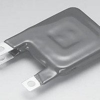
VARISTOR SQUARE INDUST 510V HB34
Manufacturer
Littelfuse Inc
Series
HB34r
Specifications of V511HB34
Energy
700J
Varistor Voltage
820V
Current-surge
40kA
Number Of Circuits
1
Maximum Ac Volts
510VAC
Maximum Dc Volts
675VDC
Package / Case
34mm Square
Technology
Metal Oxide
Capacitance Value
2500pF
Clamping Current
200A
Clamping Voltage
1350V
Lead Style
Solder Lug
Ac Voltage Rating (max)
510VAC
Dc Voltage Rating (max)
675VDC
Operating Temp Range
-55C to 85C
Mounting
Through Hole
Surge Current (max)
40000A
Lead Spacing
22mm
Product Length (mm)
37mm
Product Depth (mm)
8.8mm
Product Height (mm)
47.5mm
Product
MOV
Voltage Rating Dc
675 V
Voltage Rating Ac
510 V
Peak Surge Current
40 KA
Capacitance
2500 pF
Operating Temperature Range
- 55 C to + 85 C
Dimensions
34 mm Dia.
Termination Style
Solder Terminal
Lead Free Status / RoHS Status
Contains lead / RoHS non-compliant
Lead Free Status / RoHS Status
Compliant, Contains lead / RoHS non-compliant


Varistor Products
High Energy Industrial
HB34, HF34 and HG34 Varistor Series
Absolute Maximum Ratings
Continuous:
Transient:
Operating Ambient Temperature Range (T A ) . . . . . . . . . . . . . . . . . . . . . . . . . . . . . . . . . . . . . . . . . . . . . . . . . . . . . . . . . . . . . . . . -55 to 85
Storage Temperature Range (T STG ). . . . . . . . . . . . . . . . . . . . . . . . . . . . . . . . . . . . . . . . . . . . . . . . . . . . . . . . . . . . . . . . . . . . . . -55 to 125
Temperature Coefficient (αV) of Clamping Voltage (V C ) at Specified Test Current . . . . . . . . . . . . . . . . . . . . . . . . . . . . . . . . . . . . <0.01
CAUTION: Stresses above those listed in “Absolute Maximum Ratings” may cause permanent damage to the device. This is a stress only rating and operation of the device
at these or any other conditions above those indicated in the operational sections of this specification is not implied.
Device Ratings and Specifications
NOTE: Average power dissipation of transients not to exceed 2.0W.
1. Peak current applies to applications rated up to 115 V
2. Peak current applies to applications rated up to 123V
3. Peak current applies to applications rated up to 132V
4. Peak current applies to applications rated up to 97V
5. 40kA capability depends on applications rated up to 97Vrms. 30kA applies if >97 Vrms.
Steady State Applied Voltage:
AC Voltage Range (V M(AC)RMS ) . . . . . . . . . . . . . . . . . . . . . . . . . . . . . . . . . . . . . . . . . . . . . . . . . . . . . . . . . . . . . . . . . . . . . 110 to 750
DC Voltage Range (V M(DC) ) . . . . . . . . . . . . . . . . . . . . . . . . . . . . . . . . . . . . . . . . . . . . . . . . . . . . . . . . . . . . . . . . . . . . . . . . . 148 to 970
Peak Pulse Current (I TM )
For 8/20µs Current Wave (See Figure 2) . . . . . . . . . . . . . . . . . . . . . . . . . . . . . . . . . . . . . . . . . . . . . . . . . . . . . . . . . . . . . . . . . 40,000
Single Pulse Energy Range
For 2ms Current Square Wave (W TM ) . . . . . . . . . . . . . . . . . . . . . . . . . . . . . . . . . . . . . . . . . . . . . . . . . . . . . . . . . . . . . . . . . 220 to 1050
V111HB34
V131HB34
V141HB34
V151HB34
V181HB34
V201HB34
V251HB34
V271HB34
V301HB34
V321HB34
V331HB34
V351HB34
NUMBER
MODEL
102
(mm)
SIZE
34
34
34
34
34
34
34
34
34
34
34
34
V
V
M(AC)
110
130
140
150
180
200
250
275
300
320
330
350
(V)
RMS
CONTINUOUS
For ratings of individual members of a series, see Device Ratings and Specifications chart
V
MAXIMUM RATINGS (85
V
M(DC)
148
175
188
200
240
265
330
370
410
420
435
460
(V)
DC
RMS
RMS
RMS
RMS
. Peak Current is 30kA for applications greater than 97V
. Peak current is 30kA for applications greater than 115V
. Peak Current is 30kA for applications greater than 123V
. Peak Current is 30kA for applications greater than 132V
ENERGY
(2ms)
W
(V)
220
270
291
300
330
350
370
400
430
460
475
500
TM
o
TRANSIENT
C)
w w w . l i t t e l f u s e . c o m
CURRENT
(8/20µs)
PEAK
40,000
40,000
40,000
40,000
40,000
40,000
40,000
40,000
40,000
40,000
40,000
40,000
I
(A)
TM
5
1
2
4
MIN
(V)
156
184
198
212
254
283
354
389
433
462
467
495
RMS
RMS
RMS
RMS
.
.
.
.
VARISTOR VOLTAGE
V
AT 1mA DC TEST
N(DC)
(V)
173
200
220
240
282
314
390
430
478
510
519
550
CURRENT
SPECIFICATIONS (25
MAX
(V)
190
228
248
268
310
345
429
473
526
561
570
604
Hx34 SERIES
(V
CLAMPING
MAXIMUM
VOLTAGE
C
o
(8/20µs)
C)
) AT 200A
(V)
288
345
375
405
468
533
650
730
780
830
843
894
V
C
UNITS
TYPICAL
CAPACI-
f = 1MHz
11,600
10,000
TANCE
9,000
8,000
6,800
6,350
5,000
4,500
4,100
3,800
3,750
3,600
(pF)
%/
O
O
V
V
A
J
C
C
O
C
Related parts for V511HB34
Image
Part Number
Description
Manufacturer
Datasheet
Request
R

Part Number:
Description:
FUSEHOLDER 20A MINI INLINE CRIMP
Manufacturer:
Littelfuse Inc
Datasheet:

Part Number:
Description:
FUSEHOLDER BODY ATO INLINE PNLMT
Manufacturer:
Littelfuse Inc
Datasheet:

Part Number:
Description:
FUSE 2A 63V FAST 1206
Manufacturer:
Littelfuse Inc
Datasheet:
Part Number:
Description:
FUSE 1.25A 63V FAST 1206
Manufacturer:
Littelfuse Inc
Datasheet:
Part Number:
Description:
FUSE .250A 125V FAST 1206
Manufacturer:
Littelfuse Inc
Datasheet:
Part Number:
Description:
FUSE 4A 32V FAST 1206
Manufacturer:
Littelfuse Inc
Datasheet:
Part Number:
Description:
FUSE 1.75A 63V FAST 1206
Manufacturer:
Littelfuse Inc
Datasheet:

Part Number:
Description:
FUSE 1A 32V FST 0603 LEADFREE TR
Manufacturer:
Littelfuse Inc
Datasheet:

Part Number:
Description:
FUSE 1A 32V FAST SLIM 0402
Manufacturer:
Littelfuse Inc
Datasheet:

Part Number:
Description:
FUSE 2A 125V FAST NANO2 SMD
Manufacturer:
Littelfuse Inc
Datasheet:

Part Number:
Description:
FUSE .250A 125V FAST NANO2 SMD
Manufacturer:
Littelfuse Inc
Datasheet:

Part Number:
Description:
FUSE .500A 125V FAST NANO2 SMD
Manufacturer:
Littelfuse Inc
Datasheet:

Part Number:
Description:
FUSE 1.5A 125V FAST NANO2 SMD
Manufacturer:
Littelfuse Inc
Datasheet:

Part Number:
Description:
FUSE 4A 125V FAST NANO2 SMD
Manufacturer:
Littelfuse Inc
Datasheet:

Part Number:
Description:
FUSE 1A 125V FAST NANO2 SMD
Manufacturer:
Littelfuse Inc
Datasheet: