DVIULC6-4SC6 STMicroelectronics, DVIULC6-4SC6 Datasheet - Page 6
DVIULC6-4SC6
Manufacturer Part Number
DVIULC6-4SC6
Description
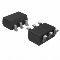
IC ESD PROTECTION LO CAP SOT23-6
Manufacturer
STMicroelectronics
Datasheet
1.DVIULC6-4SC6.pdf
(12 pages)
Specifications of DVIULC6-4SC6
Voltage - Reverse Standoff (typ)
5V
Voltage - Breakdown
6V
Polarization
4 Channel Array - Bidirectional
Mounting Type
Surface Mount
Package / Case
SOT-23-6
Applications
General Purpose
Number Of Circuits
4
Voltage - Working
6V
Voltage - Clamping
12V
Technology
Diode Array
Polarity
Bidirectional
Channels
4 Channels
Breakdown Voltage
6 V
Termination Style
SMD/SMT
Capacitance
1 pF
Dimensions
1.75 mm W x 3.05 mm L x 1.3 mm H
Diode Type
Low Capacitance / ESD Protection
Clamping Voltage Vc Max
17V
Diode Case Style
SOT-23
No. Of Pins
6
Lead Free Status / RoHS Status
Lead free / RoHS Compliant
Power (watts)
-
Lead Free Status / Rohs Status
Lead free / RoHS Compliant
Other names
497-5237-2
Available stocks
Company
Part Number
Manufacturer
Quantity
Price
Company:

Part Number:
DVIULC6-4SC6
Manufacturer:
ST
Quantity:
30 000
Part Number:
DVIULC6-4SC6
Manufacturer:
ST
Quantity:
20 000


Technical information
3
3.1
Note:
3.2
6/12
Technical information
Surge protection
The DVIULC6-4SC6 is particularly optimized to perform ESD surge protection based on the
rail to rail topology.
The clamping voltage V
with: V
V
Calculation example
We can assume that the value of the dynamic resistance of the clamping diode is typically:
For an IEC 61000-4-2 surge Level 4 (Contact Discharge: V
V
We find:
The calculations do not take into account phenomena due to parasitic inductances.
Surge protection application example
If we consider that the connections from the pin V
plane are two tracks 10 mm long and 0.5 mm wide, we can assume that the parasitic
inductances, L
due to the rise time of this spike (tr = 1 ns), the voltage V
L
The dI/dt is calculated as: dI/dt = Ip/tr = 24 A/ns for an IEC 61000-4-2 surge level 4 (contact
discharge V
The over voltage due to the parasitic inductances is: L
By taking into account the effect of these parasitic inductances due to unsuitable layout, the
clamping voltage will be:
We can reduce as much as possible these phenomena with simple layout optimization.
This is the reason why some recommendations have to be followed (see
to ensure good ESD
W
F
BUS
.dI/dt.
= forward drop voltage, V
V
V
R
V
V
V
V
= +5 V, and, in a first approximation, we assume that: I
CL
CL
CL
CL
CL
CL
d
F
= 1.4
= V
+ = V
- = - V
+ = +39 V
- = -34 V
+ = +39 + 144 = 183 V
- = -34 - 144 = -178 V
g
T
= 8 kV, R
+ R
BUS
W
F,
and V
for negative surges
of these tracks are about 6 nH. So when an IEC 61000-4-2 surge occurs,
d
.I
+ V
p
protection).
F,
T
g
CL
for positive surges
= 1.2 V.
= 330
can be calculated as follows:
T
= forward drop threshold voltage)
Doc ID 11599 Rev 2
BUS
to V
W
.dI/dt = 6 x 24 = 144 V
CL
CC
g
has an extra value equal to
= 8 kV, R
p
and from GND to PCB GND
= V
g
/ R
g
g
= 330
= 24 A.
Section 3.3: How
DVIULC6-4SC6
),
Related parts for DVIULC6-4SC6
Image
Part Number
Description
Manufacturer
Datasheet
Request
R

Part Number:
Description:
IC ESD PROT LOCAP 2LINE SOT-666
Manufacturer:
STMicroelectronics
Datasheet:

Part Number:
Description:
IC ESD PROTECTION LO CAP 6VFQFPN
Manufacturer:
STMicroelectronics
Datasheet:

Part Number:
Description:
STMicroelectronics [RIPPLE-CARRY BINARY COUNTER/DIVIDERS]
Manufacturer:
STMicroelectronics
Datasheet:
Part Number:
Description:
STMicroelectronics [LIQUID-CRYSTAL DISPLAY DRIVERS]
Manufacturer:
STMicroelectronics
Datasheet:

Part Number:
Description:
BOARD EVAL FOR MEMS SENSORS
Manufacturer:
STMicroelectronics
Datasheet:
Part Number:
Description:
NPN TRANSISTOR POWER MODULE
Manufacturer:
STMicroelectronics
Datasheet:
Part Number:
Description:
TURBOSWITCH ULTRA-FAST HIGH VOLTAGE DIODE
Manufacturer:
STMicroelectronics
Datasheet:
Part Number:
Description:
Manufacturer:
STMicroelectronics
Datasheet:
Part Number:
Description:
DIODE / SCR MODULE
Manufacturer:
STMicroelectronics
Datasheet:
Part Number:
Description:
DIODE / SCR MODULE
Manufacturer:
STMicroelectronics
Datasheet:
Part Number:
Description:
Search -----> STE16N100
Manufacturer:
STMicroelectronics
Datasheet:
Part Number:
Description:
Search ---> STE53NA50
Manufacturer:
STMicroelectronics
Datasheet: