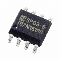
SP03-6BTG Littelfuse Inc, SP03-6BTG Datasheet - Page 3

SP03-6BTG
Manufacturer Part Number
SP03-6BTG
Description
TVS ARRAY 2CH 6V 150A 25PF SOIC8
Manufacturer
Littelfuse Inc
Series
SP03-6r
Datasheet
1.SP03-6BTG.pdf
(6 pages)
Specifications of SP03-6BTG
Package / Case
8-SOIC (3.9mm Width)
Voltage - Reverse Standoff (typ)
6V
Voltage - Breakdown
6.8V
Power (watts)
2800W
Polarization
2 Channel Array - Bidirectional
Mounting Type
Surface Mount
Applications
General Purpose
Number Of Circuits
2
Voltage - Working
6V
Technology
Diode Array
Clamping Voltage
20 V
Operating Voltage
6 V
Breakdown Voltage
6.8 V
Peak Surge Current
150 A
Peak Pulse Power Dissipation
2800 W
Maximum Operating Temperature
+ 125 C
Minimum Operating Temperature
- 55 C
Dimensions
4 (Max) mm W x 5 (Max) mm L x 1.65 (Max) mm H
Diode Type
Bidirectional TVS
Clamping Voltage Vc Max
20V
Diode Case Style
SOIC
No. Of Pins
8
Peak Pulse Current Ippm
150A
Reverse Stand-off Voltage Vrwm
6V
Rohs Compliant
Yes
Filter Terminals
SMD
Capacitance, Cd
16pF
Breakdown Voltage Range
6.8V
Clamping Voltage 8/20us Max
20V
Operating Temperature Range
-55°C To +125°C
Lead Free Status / RoHS Status
Lead free / RoHS Compliant
Voltage - Clamping
-
Lead Free Status / Rohs Status
Lead free / RoHS Compliant
Other names
F2876TR
Available stocks
Company
Part Number
Manufacturer
Quantity
Price
Part Number:
SP03-6BTG
Manufacturer:
LITTELFUSE/力特
Quantity:
20 000
Specifications are subject to change without notice.
Please refer to http://www.littelfuse.com for current information.
©2010 Littelfuse, Inc.
Figure 1: Non-repetitive Peak Pulse Current vs. Pulse Time
Figure 3: Pulse Waveform
Figure 5: Capacitance vs. Reverse Voltage
100
80
60
40
20
1000
0
100
10
20
18
16
14
12
10
0
1
8
6
4
2
0
0
1
5
1
Line-to-Ground
10
2
10
15
Pulse decay time (μs)
Reverse Voltage (V)
Time, μs
3
20
Line-to-Line
4
25
100
30
5
SPA™ Silicon Protection Array Products
Low Capacitance TVS protection for high-speed data interfaces
35
6
40
1000
Revised: February 9, 2010
7
161
Figure 2: Current Derating Curve
Figure 4: Clamping Voltage vs. Peak Pulse Current
Figure 6: Forward Voltage vs. Forward Current
120
100
80
60
40
20
7
6
5
4
3
2
1
0
0
25
20
15
10
5
0
0
0
0
10
20
20
20
40
30
Ambient Temperature (C)
I
P
Peak Impulse Current (A)
60
Forward Current (A)
40
Line-to-Line
40
80
50
Ground-to-Line
60
60
100
Line-to-Ground
70
120
80
SP03-6 (SO-8) Series
80
140
90
160
100
100


