1812L110PR Littelfuse Inc, 1812L110PR Datasheet

PTC 1.1A 6VDC RESETTABLE 1812L

1812L110PR

Manufacturer Part Number
1812L110PR
Description
PTC 1.1A 6VDC RESETTABLE 1812L
Manufacturer
Littelfuse Inc
Series
POLYFUSE® 1812Lr
Datasheets

Specifications of 1812L110PR

Package / Case
1812 (4532 Metric)
R Min/max
0.040 ~ 0.210 Ohm
Voltage - Max
6V
Time To Trip
0.3s
Current - Hold (ih) (max)
1.1A
Current - Trip (it)
2.2A
Current - Max
100A
Hold Current
1.1 Amps
Trip Current
2.2 Amps
Current Rating (max)
40 Amps
Resistance
0.226 Ohms
Maximum Voltage
6 VoltsDC
Termination Style
SMD/SMT
Mounting Style
SMD/SMT
Current Rating
40 Amps
Dimensions
4.47 mm L x 3.15 mm W x 0.61 mm H
Operating Temperature Range
- 40 C to + 85 C
Holding Current
1.1A
Tripping Current
2.2A
Initial Resistance Max
0.21ohm
Operating Voltage
6VDC
Ptc Fuse Case
1812
External Depth
0.61mm
Fuse Terminals
SMD Caps
Rohs Compliant
Yes
Lead Free Status / RoHS Status
Lead free / RoHS Compliant
Lead Free Status / RoHS Status
Lead free / RoHS Compliant, Lead free / RoHS Compliant
Other names
1812L110-C
1812L110C
F2152TR

Available stocks

Company
Part Number
Manufacturer
Quantity
Price
Part Number:
1812L110PR
Manufacturer:
LITTLEFUSE
Quantity:
55 000
Part Number:
1812L110PR
Manufacturer:
LITTELFUSE/力特
Quantity:
20 000
Part Number:
1812L110PR-T
Manufacturer:
Sumida
Quantity:
1 775
Part Number:
1812L110PRC
Manufacturer:
Coilcraft
Quantity:
2 550
Part Number:
1812L110PRN
Manufacturer:
Littelfuse
Quantity:
2 150
Part Number:
1812L110PRT
Manufacturer:
JAE
Quantity:
30 138
© 2010 Littelfuse, Inc
Specifications are subject to change without notice.
Please refer to www.littelfuse.com/series/1812L.html for current information.
I
I
V
I
Caution: Operation beyond the specified rating may result in damage and possible arcing and flame.
1 Effective September 15, 2009 onward, all 1812L PTC products will be manufactured Halogen Free (HF). Existing Non-Halogen Free 1812L PTC products will continue to be
sold until supplies are depleted. Effective January 1, 2010, all 1812L PTC product will be manufactured and sold as Halogen Free by default, and the “HF” part number suffix
code will be discontinued -- Refer to Part Ordering Number System and Packaging Options sections for additional information.
2 Some older references to these devices may include “–C“ in the Part Number. The “–C“ should be omitted when placing new orders for the device.
3 Part numbers ending in “TH” refer to new lower profile devices. For these items the “TH” suffix must be included in the ordering instructions.
Please refer also to the Dimensions and Part Ordering Number System sections of this document for additional information. Orders for the original thicker product (No TH in
part number) may be accepted in some instances through October 31, 2009. Please contact Littelfuse for additional information or arrangements.
hold
trip
max
max
Agency Approvals
AGENCY
Electrical Characteristics
1812L200TH
1812L260TH
= Trip current: minimum current at which the device will trip in 20°C still air.
Part Number
= Hold current: maximum current device will pass without tripping in 20°C still air.
= Maximum fault current device can withstand without damage at rated voltage (V
1812L035/30
1812L050/30
1812L075/24
1812L075/33
1812L150/12
1812L150/24
1812L160/12
1812L260/12
1812L110/16
1812L110/24
1812L110/33
1812L125
= Maximum voltage device can withstand without damage at rated current (I max)
1812L125/6
1812L050
1812L075
1812L125
1812L150
1812L160
1812L110
1812L020
1812L300
1812L010
1812L014
/16
2
2
2
2
AGENCY FILE NUMBER
E183209
R50119118
2
2
2,3
2,3
1812L Series
LF035-30
LF050-30
LF075-24
LF075-33
LF150-24
LF260-12
LF110-24
LF110-33
LF125-16
LF150-12
LF160-12
Marking
LF110-16
LF125-6
LF020
LF050
LF075
LF125
LF150
LF160
LF200
LF260
LF300
LF010
LF014
LF110
0.20
0.35
0.50
0.50
0.75
0.75
0.75
2.00
2.60
2.60
3.00
I
0.10
0.14
1.25
1.25
1.25
1.50
1.50
1.50
1.60
1.60
1.10
1.10
1.10
1.10
(A)
hold
3.00
3.00
3.00
5.00
5.00
5.00
0.30
0.34
0.40
0.75
1.00
1.00
1.50
1.50
1.50
2.20
1.95
1.95
1.95
2.50
2.50
2.50
2.80
2.80
3.50
I
(A)
trip
Surface Mount > 1812L Series
POLYFUSE
(Vdc)
V
13.2
30
60
30
30
15
30
24
33
16
24
33
15
16
12
24
12
12
6
6
8
8
8
8
6
max
I
100
100
100
100
100
100
100
100
100
100
100
100
100
100
100
100
100
100
100
100
(A)
20
20
20
20
10
max
Revised: July 12, 2010
max
typ.
(W)
)
0.8
0.8
0.8
0.8
0.8
0.8
0.8
0.8
0.8
0.8
0.8
0.8
0.8
0.8
0.8
0.8
0.8
0.8
0.8
0.8
0.8
0.8
0.8
0.8
0.8
P
®
d
39
Resettable PTCs
P
R
R
R
Current
d
min
typ
1max
Description
The 1812L Series PTC provides surface mount overcurrent
protection for applications where resettable protection is
desired.
Features
Applications
Max. Time To Trip
0.50
8.00
8.00
8.00
8.00
8.00
8.00
8.00
8.00
8.00
8.00
8.00
8.00
8.00
8.00
8.00
8.00
8.00
8.00
8.00
8.00
8.00
8.00
8.00
= Power dissipated from device when in the tripped state at 20°C still air.
1.50
(A)
= Typical resistance of device in initial (un-soldered) state.
for motherboards and
peripherals
= Minimum resistance of device in initial (un-soldered) state.
and halogen-free
= Maximum resistance of device at 20°C measured one hour after tripping or reflow
soldering of 260°C for 20 sec.
(Sec.)
Time
0.15
0.02
0.02
0.15
0.15
0.20
0.20
0.20
0.30
0.30
0.50
0.50
0.40
0.40
0.40
0.30
0.50
1.00
1.00
2.00
2.50
5.00
4.00
1.50
1.50
1
0.800
0.800
0.150
0.150
0.100
0.040
0.060
0.060
0.060
0.050
0.050
0.050
0.040
0.040
0.040
0.030
0.030
0.020
1.600
1.500
0.110
0.110
0.015
0.015
0.012
R
(Ω)
Resistance
min
15.000
6.000
5.000
5.000
0.400
0.200
0.200
1.000
1.000
0.450
0.290
0.210
0.180
0.250
0.140
0.140
0.120
0.100
0.100
0.070
0.047
0.055
0.040
0.110
0.110
R
(Ω)
1max
temperature solders
protection
Agency Approvals
X
X
X
X
X
X
X
X
X
X
X
X
X
X
X
X
X
X
X
X
X
X
X
X
X
X
X
X
X
X
X
X
X
X
X
X
X
X
X
X
X
X
X
X
X
X
X
X
X
X
1812L Series

Related parts for 1812L110PR

1812L110PR Summary of contents

Page 1

Series Agency Approvals AGENCY AGENCY FILE NUMBER E183209 R50119118 Electrical Characteristics I I hold trip Part Number Marking (A) (A) 1812L010 LF010 0.10 0.30 1812L014 LF014 0.14 0.34 1812L020 LF020 0.20 0.40 1812L035/30 LF035-30 0.35 0.75 2 LF050 0.50 ...

Page 2

POLYFUSE Temperature Rerating -40°C -20°C Part Number 1812L010 0.16 0.14 1812L014 0.23 0.19 1812L020 0.29 0.26 1812L035/30 0.50 0.45 1812L050 0.77 0.68 1812L050/30 0.77 0.68 1812L075 1.15 1.01 1812L075/24 1.06 0.95 1812L075/33 1.10 1.00 1812L110 1.59 1.43 1812L110/16 1.58 1.43 ...

Page 3

Average Time Current Curves 1000 100 10 1 0.10 0 Current in Amperes The average time current curves and Temperature Rerating curve performance is affected by a number or variables, and these curves provided as guidance only. Customer ...

Page 4

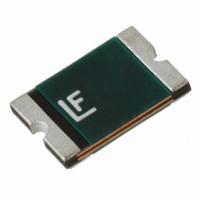
POLYFUSE Dimensions MARKING CODE VARIES WITH AMPERAGE AND VOLTAGE RATING (See Electrical Characteristics Table) SHOWN ARE: - 1.1A/6V RATING (LEFT) - 1.1A/33V RATING (RIGHT) A Top 110 B View 3.45 mm Bottom 110 Pad View Layout D E 1.78mm (.070”) ...

Page 5

... Yes 1812L075PRHF Yes 1812L075 1812L075PR 1812L075/24DRHF Yes 1812L75/24 1812L075/24DR 1812L075/33DRHF Yes 1812L75/33 1812L075/33DR 1812L110PRHF Yes 1812L110 1812L110PR 1812L110/16DRHF Yes 1812L110/16 1812L110/16DR 1812L110/24 1812L110/24DR Yes 1812L110/33MRHF Yes 1812L110/33 1812L110/33MR 1812L125DRHF Yes 1812L125 1812L125DR 1812L125/6PRHF Yes 1812L125/6 1812L125/6PR 1812L125/16 ...

Page 6

POLYFUSE Tape and Reel Specifications TAPE SPECIFICATIONS: EIA-481-1 (mm) 1812L020 1812L035/30 1812L050 1812L075 1812L110 1812L125/6 1812L150 1812L160 1812L200TH 12.00+0.30-0.10 W 5.50+/- 0.05 F 1.75+/- 0. 1.50+0. 1.50+0. 4.00+/- 0. 8.00+/- 0.10 P ...

Related keywords