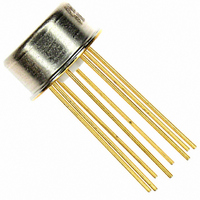
5962-8773802GA Analog Devices Inc, 5962-8773802GA Datasheet - Page 10

5962-8773802GA
Manufacturer Part Number
5962-8773802GA
Description
IC OPAMP GP 600KHZ LP TO99-8
Manufacturer
Analog Devices Inc
Datasheet
1.5962-8773802GA.pdf
(16 pages)
Specifications of 5962-8773802GA
Slew Rate
0.3 V/µs
Amplifier Type
General Purpose
Number Of Circuits
1
Gain Bandwidth Product
600kHz
Current - Input Bias
2.4nA
Voltage - Input Offset
25µV
Voltage - Supply, Single/dual (±)
±3 V ~ 18 V
Operating Temperature
-55°C ~ 125°C
Mounting Type
Through Hole
Package / Case
TO-99-8, Metal Can
Rail/rail I/o Type
No
Number Of Elements
1
Common Mode Rejection Ratio
120dB
Input Offset Voltage
0.025@±15VmV
Single Supply Voltage (typ)
Not RequiredV
Dual Supply Voltage (typ)
±5/±9/±12/±15V
Voltage Gain In Db
133.98dB
Power Supply Rejection Ratio
110.46dB
Power Supply Requirement
Dual
Shut Down Feature
No
Single Supply Voltage (min)
Not RequiredV
Single Supply Voltage (max)
Not RequiredV
Dual Supply Voltage (min)
±3V
Dual Supply Voltage (max)
±22V
Technology
Bipolar
Operating Temp Range
-55C to 125C
Operating Temperature Classification
Military
Mounting
Through Hole
Pin Count
8
Package Type
TO-99
Lead Free Status / RoHS Status
Lead free / RoHS Compliant
Current - Supply
-
Output Type
-
Current - Output / Channel
-
-3db Bandwidth
-
Lead Free Status / RoHS Status
Not Compliant, Lead free / RoHS Compliant
Other names
Q3964209
Available stocks
Company
Part Number
Manufacturer
Quantity
Price
OP77
TEST CIRCUITS
100Ω
100Ω
Figure 22. Typical Low-Frequency Noise Test Circuit
INPUT
Figure 21. Typical Offset Voltage Test Circuit
NOTES
*
1 PER BOARD
Figure 23. Optional Offset Nulling Circuit
+
–
INPUT REFERRED NOISE =
10kΩ
2
3
50Ω
OP77
2.5MΩ
Figure 24. Burn-In Circuit
*
*
10kΩ
V+
V–
4
7
+
+
2
3
10µF
10µF
2
3
OP77
6
1
OP77
OP77
100kΩ
V–
+18V
–18V
200kΩ
3.3kΩ
8
4
20kΩ
7
4
10Ω
10Ω
0.1µF
7 6
V
6
OS
25,000
4.7µF
(≈10Hz FILTER)
V
=
O
0.1µF
4000
V
O
V+
OUTPUT
V
O
OUTPUT
Rev. E | Page 10 of 16
Actual open-loop voltage gain can vary greatly at various output
voltages. All automated testers use endpoint testing and therefore
only show the average gain. This causes errors in high closed-
loop gain circuits. Because this is difficult for manufacturers to
test, users should make their own evaluations. This simple test
circuit makes it easy. An ideal op amp would show a horizontal
scope trace.
This is the output gain linearity trace for the new OP77. The
output trace is virtually horizontal at all points, assuring
extremely high gain accuracy. The average open-loop gain is
truly impressive—approximately 10,000,000.
NOTES
1. GAIN NOT CONSISTANT. CAUSES NONLINEAR ERRORS.
2. A
3. CHECK SPECIFICATION TABLE 1 AND TABLE 2 FOR PERFORMANCE.
V
VO
IN
10kΩ
= ±10V
SPEC IS ONLY PART OF THE SOLUTION.
–10V
1MΩ
10Ω
Figure 26. Output Gain Linearity Trace
Figure 25. Open-Loop Gain Linearity
100kΩ
R
0V
V
L
Y
V
X
–10V
TYPICAL PRECISION
A
R
VO
L
= 2kΩ
+10V
OP AMP
650V/mV
0V
V
Y
+10V
V
X
V
X


